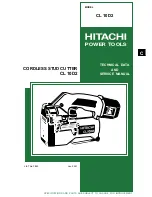
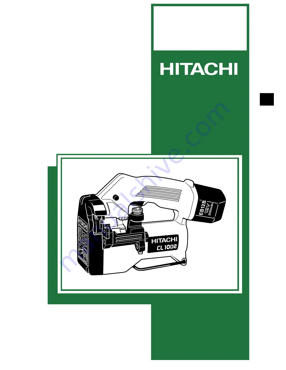
background image

POWER TOOLS

TECHNICAL  DATA

AND

SERVICE  MANUAL

CORDLESS STUD CUTTER

CL 10D2

SPECIFICATIONS  AND  PARTS  ARE  SUBJECT  TO  CHANGE  FOR  IMPROVEMENT

LIST No. F842

Jan. 2001

C

MODEL

CL 10D2

Summary of Contents for CL 10D2

Page 1: ...POWER TOOLS TECHNICAL DATA AND SERVICE MANUAL CORDLESS STUD CUTTER CL 10D2 SPECIFICATIONS AND PARTS ARE SUBJECT TO CHANGE FOR IMPROVEMENT LIST No F842 Jan 2001 C MODEL CL 10D2 ...

Page 2: ...Notice for use Specifications and parts are subject to change for improvement Refer to Hitachi Power Tool Technical News for further information ...

Page 3: ... WITH SIMILAR PRODUCTS 9 6 1 Specification Comparisons 9 7 PRECAUTIONS IN SALES PROMOTION 10 7 1 Safety Instructions 10 7 2 Suggestions and Precautions for Efficient Use of Charger 14 8 REPAIR GUIDE 15 8 1 Precautions in Disassembly and Reassembly 15 8 2 Reassembly 21 8 3 Precautions in Disassembly and Reassembly of Battery Charger 27 9 STANDARD REPAIR TIME UNIT SCHEDULES 28 Assembly Diagram for C...

Page 4: ...en though it uses the 12 V battery while the Model CL 10D using the 9 6 V battery weighs 3 4 kg The Model CL 10D2 becomes low price thanks to renewing the manufacturing processes and sharing components with other models In addition the Model CL 10D2 is capable of cutting up to 550 studs per single charge when cutting M10 soft steel studs using the 12 V NiMH battery with nominal capacity 3 0 Ah Thi...

Page 5: ...tting by cut off machine Excellent working efficiency Clean cutting without sparks chips and noise 24 mm minumum cutting length Special steel made long service life cutter Service life of cutters increased through use of four cutting edges Convenient stud mounting hole facilitates cutting studs to specified lengths Convenient hook facilitates operation in high places Cordless Cam operated auto ret...

Page 6: ...chine for example When mounting luminaiers however often only two studs are cut in one spot This means that the cut off machine must be moved from one spot to another over a wide area The Model CL 10D2 is compact lightweight and cordless so it is easily transportable and particularly convenient for cutting off hanged studs In addition it is capable of cutting up to 550 studs per single charge so i...

Page 7: ...time is required for deburring after the studs have been cut In actual tests the Model CL 10D2 is approximately three times more efficient than cut off machines or disc grinders Table 1 Cutting time comparison Table 2 Number of studs that can be cut per battery charge Fig 9 Four cutting edges Reverse cutters by turning each top to bottom Cutter 2 Reverse cutters by turning each side to side Revers...

Page 8: ...ngles in order to prevent damage of the lagging As illustrated the Model CL 10D2 permits cutting of studs within an L shaped angle measuring 25 mm x 25 mm x 3 mm t Fig 10 Minimum cutting length 7 Convenient hook facilitates operation in high places When performing equipment installation work in high places cutting of hanging studs is often only one of several jobs that must be performed Accordingl...

Page 9: ... to the front of the main body as shown in Fig 12 2 The stud mounting hole is particularly convenient when it is necessary to cut several studs at the same length from for example the surface of a ceiling Fig 12 1 Length alignment to rear of main body Fig 12 2 Length alignment to front of main body Fig 12 Stud mounting hole facilitates cutting to specified lengths 9 Cam operated auto return mechan...

Page 10: ...approximately 1 000 cycles in case of Model UC 14YF2 Nominal capacity 2 0 Ah Sealed cylindrical nickel metal hydride batteries Nominal voltage DC 12V Nominal life Charging discharging approximately 500 cycles in case of Model UC 14YF2 Nominal capacity 3 0 Ah Battery Type EB 1230H Sealed power source Single phase AC 50 60 Hz Voltage Depending on the order specification Power input 44 W Charging sys...

Page 11: ...torage battery or charger is faulty Charging not possible because storage battery temperature is too high Pilot lamp indications UC 14YF2 5 2 Optional Accessories Cutter ass y Stud size Code No Combining cutters and spacers M10 x 1 5 M10 Cutter 2 M10 Spacer 2 308565 W3 8 x 1 5875 M6 x 1 M8 x 1 25 308563 308564 M8 Cutter 2 M8 Spacer 2 M6 Cutter 2 M6 Spacer 2 W3 8 Cutter 2 998479 Trimmer Stud size C...

Page 12: ... kg 7 5 lbs including battery 2 7 kg 5 95 lbs excluding cord 2 4 550 2 6 140 2 4 NA Cutting time M10 Number of cuttings per battery charge M10 Type of motor DC magnet AC single phase series commutator motor DC magnet Trigger switch with forward reverse changeover pushing button with brake Trigger switch with forward reverse changeover pushing button with brake and variable Trigger switch with forw...

Page 13: ...the unit If this order is reserved the charger may not function properly 4 Ensure the power source voltage is the same as that indicated on the name plate of the Charger Use of any other power source DC outlet fuel powered generator etc will cause the Charger to overheat and burn out 5 Do not use any voltage increasing equipment transformer etc between the power source and the Charger If the Charg...

Page 14: ...ngaged with the threads of the stud as illustrated in Fig 13 the excessive concentration of load on the blade portion will cause it to break after only a few cutting operations The length of stud cut off should be at least 10 mm Instruct customers to confirm that all of the threads of the cutter engage the threads of the stud during cutting 13 Care should be exercised when performing cutting in na...

Page 15: ...of the stud cutter will become defective after a short period of operation 15 Never attempt cutting operation at the position If the storage battery charge runs out and motor rotation stops during cutting pull the switch in the position while pressing the forward reverse changeover button from the left as shown in Fig 17 to disengage the cutter from the stud As the motor is locked at the position ...

Page 16: ...htened it will cause damage to the cutters and the main body of the tool Instruct the customer to ensure that the cutters are properly mounted 20 When operating the tool in high places the falling cut off stud portions are extremely dangerous The customers should be cautioned to be particularly careful at such times In addition the tool should be stored in a safe secure place when not in use 21 Wh...

Page 17: ...o the Model UC 14YF2 Charger This is because the built in thermostat functions to stop the charging when the temperature of the storage batteries reaches 40 C 104 F or more In such a case the customer should be advised to place the batteries in a shaded area with a good airflow and allow sufficient cooling before recharging This phenomenon is common to all existing batteries which employ temperatu...

Page 18: ...3 to the position and depress the trigger switch until Bracket A 42 opens Then release the trigger switch and remove the storage battery Remove the two Special Bolts M5 x 9 50 from the two Cutter Ass y M8 52 with the Hex Bar Wrench 4 mm 11 standard accessory Insert the storage battery in the main body Depress the trigger switch keeping the Pushing Button set to the position until Bracket A 42 is p...

Page 19: ... the two Seal Lock Screws W SP Washer M4 x 12 40 and remove the Return Plate 41 c Removal of the Gear Cover 19 Fig 20 Remove the four Tapping Screws W Flange D5 x 25 Black 17 and the two Tapping Screws D5 x 35 43 Hold Bracket B 44 and Bracket A 42 and remove them being careful not to move Bracket A 42 Then the Second Gear 22 and the Third Pinion 21 can be removed Fig 21 Fig 20 Fig 21 Press fitted ...

Page 20: ...Remove the Final Gear 35 and the two Feather Keys 5 x 5 x 10 56 Then the Cam Shaft 55 can be removed e Removal of the bracket ass y Figs 23 and 24 Remove the three Hex Socket Hd Bolts M5 x 12 34 from Bracket B 44 with the Hex Bar Wrench 4 mm 11 Holding Bracket A 42 and Bracket B 44 remove the bracket ass y being careful not to make the Return Spring 18 jump up 34 56 55 36 35 18 42 44 ...

Page 21: ...Supporting around the head of Bolt A 39 of Bracket A 42 push the screw side of Bolt A 39 with a hand press to separate Bracket A 42 from Bracket B 44 ii Removal of Roller A 53 Fig 26 The Roller Pin 54 that secures Roller A 53 is press fitted into Bracket A 42 Remove the Roller Pin 54 by pushing in either direction with a hand press Then Roller A 53 can be removed Push with a large hand press Hold ...

Page 22: ...at blade screwdriver Then the Hook 6 can be removed b Removal of Housing B 2 Remove the nine Tapping Screws W Flange D4 x 20 Black 8 that secure Housing A 2 to Housing B 2 Holding the compartment of the Gear Cover 19 in Housing A 2 and Housing B 2 or the compartment of the battery remove Housing B 2 carefully Fig 27 Housing A 2 Housing B 2 10 8 6 ...

Page 23: ...t 15 Remove the Motor 33 and the Second Pinion 28 from Housing A 2 Fig 28 15 3 4 14 12 13 28 33 3 Power supply unit section Remove the internal wires coming from the Motor 33 and the Switch Ass y 14 from the Switch 13 with a soldering iron CAUTION Do not apply heat to the Switch 13 for a long time with the soldering iron when removing the internal wires Otherwise the electronic circuit in the Swit...

Page 24: ...removed Remove the Needle 30 and the Idle Gear 29 8 2 Reassembly Reassembly can be accomplished by following the disassembly procedures in reverse However particular attention should be given to the following items 1 Reassembly of the power supply unit section Be sure to perform wiring connections as indicated in the wiring diagram below Fig 30 Fig 30 Fig 31 Red Blue Brown Brown Blue Black Red Bla...

Page 25: ...attling in a direction at the right angle to the straight line connecting the two Needles 30 b Planet gear Fig 33 First apply grease Nippeco SEP 3A to the inner circumference of the Ring Gear 27 Mount the pinion of the Motor 33 to the Second Pinion 28 assembled according to the above step a and mount the Ring Gear 27 Check that the Ring Gear 27 and the Second Pinion 28 are rattling If there is no ...

Page 26: ... 36 c Power supply unit Fig 33 Mount the power supply unit assembled according to the above step 1 to Housing A 2 Connect the internal wires of the Switch Ass y 14 locating the blue internal wire at the upper position and the brown internal wire at the lower position Housing A 2 and Housing B 2 are indicated with and respectively Be sure to connect the brown internal wire to the side and the blue ...

Page 27: ...e Return Spring 18 on Bracket A 42 Fig 37 iii Tighten the three Hex Socket Hd Bolts M5 x 12 34 with the Hex Bar Wrench 4 mm 11 at the specified tightening torque because they are very important for the strength Fig 38 iv Mount the Ball Bearing 629VVC2PS2L 20 to the Gear Cover 19 Fig 38 v Mount the two Feather Keys 5 x 5 x 10 56 to the Cam Shaft 55 Insert the Final Gear 35 in the proper direction M...

Page 28: ...t the maximum cutting position in the same manner as the removal procedure be careful of the spring force Fig 41 iv Tighten the four Tapping Screws W Flange D5 x 25 Black 17 and the two Tapping Screws D5 x 35 43 Fig 41 CAUTION Check that there is no scratch dust or chips on the surfaces of the cam and the roller g Reassembly of the Return Plate 41 Align the Return Plate 41 with the Roller Pin 54 a...

Page 29: ...tton 3 to the position and depress the trigger switch Check that the motor does not rotate iii Pressing the Pushing Button 3 to the position depress the trigger switch Check that the Cam Shaft 55 rotates counterclockwise in the reverse direction of Fig 42 iv Check that the Pushing Button 3 returns to the position when releasing the Pushing Button 3 Fig 42 Rotating direction of the Cam Shaft 55 whe...

Page 30: ... Machine Screw W Washers Black M4 x 20 37 1 76 0 49 N m 18 5 kgf cm 15 7 4 3 in lbs Seal Lock Screw W SP Washer M4 x 12 40 1 76 0 49 N m 18 5 kgf cm 15 7 4 3 in lbs Tapping Screw W Flange D5 x 25 Black 17 3 43 0 49 N m 35 5 kgf cm 30 5 4 3 in lbs Tapping Screw D5 x 35 43 3 43 0 49 N m 35 5 kgf cm 30 5 4 3 in lbs Hex Socket Hd Bolt M5 x 12 34 5 88 1 47 N m 60 15 kgf cm 52 2 13 in lbs Special Bolt M...

Page 31: ... x 2 Ball Bearing 609VV Retaining Ring for D15 Shaft Ring Gear Needle x 2 Idle Gear x 2 Bolt A Lock Nut M12 Bracket B Cam Shaft Stud Guide Ass y General Assembly Pushing Button Spring Terminal Support Switch Ass y Housing A B Set Motor Hook Retaining Ring E type for D4 Shaft Cover Second Gear Third Pinion Ball Bearing 629VV Ball Bearing 608VV Gear Cover Return Spring Return Plate Bracket A Roller ...

Page 32: ...ELECTRIC TOOL PARTS LIST LIST NO CORDLESS STUD CUTTER Model CL 10D2 2001 1 25 E1 F842 ...

Page 33: ...G 629VVC2PS2L 1 21 319 407 THIRD PINION 1 22 319 406 SECOND GEAR 1 23 608 VVM BALL BEARING 608VVC2PS2L 1 24 609 VVM BALL BEARING 609VVC2PS2L 1 25 939 544 RETAINING RING FOR D15 SHAFT 10 PCS 1 26 302 714 WASHER 1 27 310 254 RING GEAR 1 28 319 405 SECOND PINION 1 29 319 404 IDLE GEAR 2 30 307 609 NEEDLE 2 31 307 608 WASHER 1 32 600 1VV BALL BEARING 6001VVCMPS2L 1 33 319 413 MOTOR 1 34 998 471 HEX SO...

Page 34: ...ODE NO DESCRIPTION REMARKS NO USED PARTS CL 10D2 1 01 51 308 779 SPACER M8 10 PCS 2 52 308 564 CUTTER ASS Y M8 1 PAIR 2 INCLUD 51 53 319 399 ROLLER A 1 54 319 400 ROLLER PIN 1 55 319 394 CAM SHAFT 1 56 948 015 FEATHER KEY 5X5X10 2 ...

Page 35: ... in Japan 010125N 1 01 501 319 774 CASE 1 502 CHARGER MODEL UC 14YF2 1 503 308 569 TRIMMER M8 1 601 308 563 CUTTER ASS Y M6 1 PAIR 2 INCLUD 602 602 309 181 SPACER M6 10 PCS 2 603 308 565 CUTTER ASS Y M10 1 PAIR 2 INCLUD 604 604 308 780 SPACER M10 10 PCS 2 605 998 479 CUTTER W3 8 1 PAIR 2 606 308 568 TRIMMER M6 1 607 308 570 TRIMMER M10 1 608 308 567 TRIMMER W3 8 1 ...

Page 36: ......

Reviews: