Service manual CL2554AN / CL2854AN
- 52 -
·
So, I810 controlled rectifier is not conducting
- Q809 is conducting. So, Q808 is not conducting and Q807 is conducting
- So, Q807 collector is connected to the ground and I810 controlled rectifier gate pin is
set to low (no conducting)
·
So, current from 11V DC voltage (from T801 SMPS transformer pin 13) does not flow through
Q811 and Q810 transistors but flows through I806 IC error amplifier
- Q809 is conducting. So, Q810 is not conducting and no current flows from Q810
collector to the ground
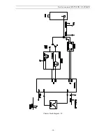
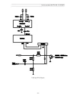
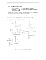
Therefore, the power supply circuit diagram is the one shown on the next paragraph
* power supply circuit diagram during TV set normal run
I 8 2 0
5 V
R E G U L A T O R
I 8 2 3
3 . 3 V
R E G U L A T O R
1 4 . 5 V ( C P 7 8 5 )
1 2 . 5 V ( C P 3 8 5 )
5 V
3 . 3 V
3
3
1
1
1 1 V
8 V
6 V
1
3
1 4 3 V ( C P 7 8 5 )
1 2 3 V - 1 1 3 V ( C P 3 8 5 )
D 8 2 0
D 8 6 0
D 8 3 0
D 8 3 1
C 8 3 2
C 8 2 3
C 8 6 1
9
1 2
1 3
1 6
2
4
C 8 1 3
R 8 2 3
R 8 1 0
1 1 V
2
3
I 8 0 6
I C E R R O R A M P L I F I E R
1 4 . 5 V
1 2 . 5 V
8 . 5 V
8 V
1 1 . 5 V
1 1 V
1 4 3 V
1 2 3 V / 1 1 3 V
T 8 0 1 S M P S T R A N S F O R M E R
D 8 0 1 . . . D 8 0 4
( G R A E T Z B R I D G E )
D
I 8 0 1
M O S F E T A N D
C O N T R O L I C
S W 8 0 1
P O W E R
S W I T C H
M A I N A C V O L T A G E
L 8 0 1
I 8 2 2
8
V
R E G U L A T O R
1
3
Power supply operation during TV set normal run
Summary of Contents for CL2554AN
Page 17: ...Service manual CL2554AN CL2854AN 16 ...
Page 21: ...Service manual CL2554AN CL2854AN 20 ...
Page 34: ...Service manual CL2554AN CL2854AN 33 5 Circuit description 5 1 Block diagram ...
Page 39: ...Service manual CL2554AN CL2854AN 38 Chassis block diagram IF ...
Page 43: ...Service manual CL2554AN CL2854AN 42 Sound signal flow diagram ...

