PRODUCT NAME
Hitachi Engine Cutter
Models
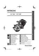
CM 75EAP
CM 75EBP
International Sales Division
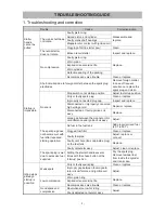
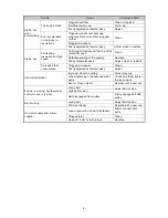
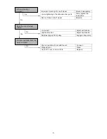
TROUBLESHOOTING GUIDE ----------------------------------------------------------------------------------------------- 1
1. Troubleshooting and correction ------------------------------------------------------------------------------- 1
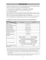
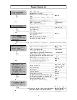
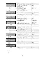
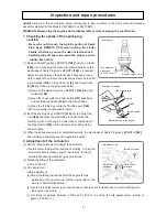
REPAIR GUIDE ------------------------------------------------------------------------------------------------------------------ 3
1. Precautions on maintenance, inspection and repair ----------------------------------------------------- 3
2. Inspection criteria for each section and consumable parts --------------------------------------------- 3
CONTENTS
Page
LIST Nos.
CM 75EAP: F070
CS 75 EBP: F071
Sep. 2014
C