


-17-
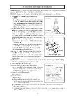
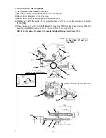
8. Adjustment of gap between the magneto rotor and ignition coil ass'y
(1) Loosen the two Bolts M4 x 18
[27]
so as to
temporarily retain the Ignition Coil Ass'y
[23]
.
(2) Insert a 0.3-mm thickness gauge into the
clearance between the Ignition Coil Ass'y
[23]
and the periphery of the magnetic steel portion
of the Magneto Rotor
[14]
.
(3) In this state, firmly tighten the two Bolts M4 x 18
[27]
.
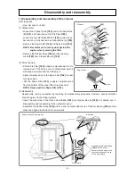
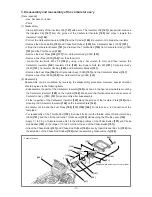
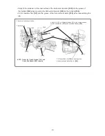
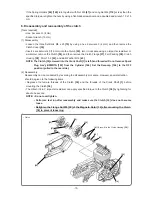
9. Electric wiring
Perform wiring according to the following figure.
(1) Connect the connector of the Cord
[21]
to the Ignition Coil Ass'y
[23]
.
(2) Connect the Earth Cord
[11]
to Crank Case (A)
[6]
using the Bolt M4 x 10
[12]
.
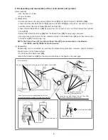
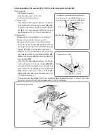
(3) Fit the Stop Switch
[196]
to the Rear Handle Set
[114]
with the “1” mark on the left side.
(4) Connect the connectors of the Cord
[21]
and Earth Cord
[11]
to the connectors of the Stop Switch
[196]
.
(5) Place the Switch Cover
[197]
on the Stop Switch
[196]
.
NOTE: Do not get the Cord [21] and the high-voltage cord pinched by other parts.
• Electric wiring
[27]
[6]
[142]
[11]
[146]
[12]
[196]
[197]
[21]
[23]
[114]
High-voltage cord
[22]
• Adjustment of gap between the magneto rotor and ignition coil
ass’y
[14]
0.2 to 0.4 mm
0.2 to 0.4 mm
[27]
[23]