


-7-
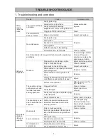
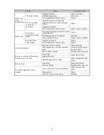
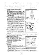
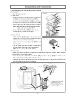
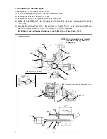
• Spark plug
• Checking for sparks
High voltage cord
Ignited sparks
[142]
Plug cap
Metallic portion of the engine
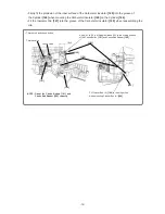
[Bold]
numbers in the descriptions below correspond to item numbers in the Parts List and exploded
assembly diagram for the Models CM 75EAP and CM 75EBP.
WARNING: Always stop the engine prior to disassembly or when replacing the cut-off wheel.
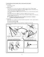
1. Checking for sparks of the spark plug
CAUTION:
•
Be careful not to touch the metallic portion of Spark
Plug Ass’y BPMR7A [142] when pulling the starter
handle; otherwise, you run the risk of electric shock.
•
Carefully wipe off any fuel around the plug to avoid a
sudden flash of fire.
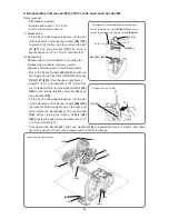
(1) Remove Spark Plug Ass’y BPMR7A
[142]
from the Cylinder
[146]
. Use a wire brush to clean off carbon deposits on the
electrodes of Spark Plug Ass’y BPMR7A
[142]
, as needed.
Adjust the gap between the electrodes if necessary. Use a
cloth to wipe off any fuel on the electrodes. Remove fuel left
in the Cylinder
[146]
, Crank Case (A)
[6]
, and Crank Case
(B)
[44]
by following the procedure below.
(a) Remove the Spark Plug Ass’y BPMR7A
[142]
from the
Cylinder
[146]
.
(b) Open the choke (with the Choke button
[191]
pushed in)
and set the Stop Switch
[196]
to the stop position.
(c) Open the throttle by pulling the Throttle Lever
[134]
.
(d) Pull the starter handle several times.
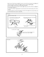
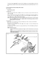
(2) Insert Spark Plug Ass’y BPMR7A
[142]
into the Plug Cap
Cord
[24]
and place the electrodes in contact with the
metallic portion of the engine. Under these conditions, set
the Stop Switch
[196]
to the startup position and pull the
starter handle.
(3) When the above steps are all completed normally, the electrodes of Spark Plug Ass’y BPMR7A
[142]
should make a snapping sound to generate sparks.
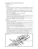
2. Adjustment of the carburetor
(1) Use the idle adjust screw to adjust the carburetor.
• Use this screw to adjust the revolutions at idling. Turning the
screw clockwise increases engine revolutions; turning it
counterclockwise decreases engine revolutions.
(2) Standard setting of the carburetor
• 2,500 ± 200 min
-1
(3) Fine adjustment
• Idling adjustment
(a) Adjust the idling revolutions after the engine is fully
warmed up. (Tip on warm-up: Let the engine idle for one
minute in half-throttled status.)
(b) Use the idle adjust screw to set revolutions so that the cut-off wheel does not start rotating while
the engine runs stably.
(c) Set idling revolutions between 2,300 and 2,700 min
-1
by using the idle adjust screw. (Adjust to
approx. 2,500 min
-1
.)
Inspection and repair procedures
Gap between
electrodes
(0.6 to 0.7 mm)
Remove carbon here.
• Idle adjust screw
Idle adjust screw
Revolutions
decrease.
Revolutions
increase.


