background image

HITACHI CML155XW LCD Monitor Service Manual (v1.0)


6

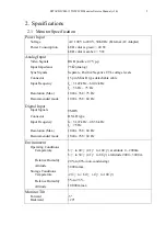
Panel Characteristics

Panel Type

Pixel Format

Pixel Pitch

Pixel Configuration

Display Area

Faceplate Coating

Luminance

Contrast Ration

White Point

Display Color

Viewing Angle

15-in (38.1 cm) XGA TFT LCD (active matrix)

1024(H) x 768(V) (1 pixel = R+G+B dot)

0.297 mm(H) x 0.297 mm(V)

R

G

B vertical stripe

304.1 mm(H) x 228.1 mm(V)

Anti-glare, and hard-coating 3H (Haze value = 28)

300 Cd/m² (typ.)

500:1 (typ.)

(x, y) = (0.29, 0.31)

16,777,216

H: -65º ~ 65º (typ.)
V: -60º ~ 50º (typ.)

Panel Characteristics

DDC2B

Power Management

Complies with EPA and DPMS

Dimension

376 mm x 381 mm x 204 mm (W x H x D)

Weight

5.5 kg

2.2


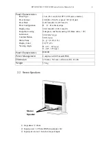
 Stereo Speakers

1)


Impedance: 8 ohms

2)


Input power: 1.2 Watts RMS (maximum) X 2

3)


Input jack: stereo 1/8-inch mini-jack input

Stereo

Speaker

Summary of Contents for CML155XW

Page 1: ...t der Service Ingenieur die Sicherheitshinweise und Hinweise zur Produktsicherheit in diesem Wartungshandbuch zu lesen SERVICE MANUAL MANUEL D ENTRETIEN WARTUNGSHANDBUCH Data contained within this Service manual is subject to alteration for improvement Les données fournies dans le présent manuel d entretien peuvent faire l objet de modifications en vue de perfectionner le produit Die in diesem War...

Page 2: ...e without danger of electrical shock The service technician must make sure that no protective device built into the instrument by the manufacturer has become defective or inadvertently damaged during servicing CE MARK 1 HITACHI products may contain the CE mark on the rating plate indicating that the product contains parts that have been specifically approved to provide electromagnetic compatibilit...

Page 3: ...ts 7 3 Control Buttons and Functions 8 3 1 User Control Buttons 8 3 2 Power LED 9 3 2 Tilting the Displays 9 4 Disassembly Instructions 10 5 General Connection and Applications 12 5 1 Connecting the Monitor to the Computer 12 5 2 Connecting the Monitor to the AV device 14 6 Electronic Circuit Description 16 6 1 Main Board Circuit 16 6 2 Audio Board Circuit 18 6 3 Keyboard Circuit 18 6 4 Inverter C...

Page 4: ...ram Appendix B Mainboard Circuit Diagrams Appendix C Audio Board Circuit Diagram Appendix D Keyboard Circuit Diagram Appendix F Troubleshooting Flow Chart Appendix G Proposed Repair Parts List Appendix H Mechanical Disassembly Appendix I PCB Layout Appendix E Inverter Circuit Diagram ...

Page 5: ... the customer a thorough safety test must be performed to verify that the display is safe to operate without danger of shock 1 2 Product Safety Notice 1 Many electrical and mechanical parts in this chassis provide special visual safety protection The protection afforded by them cannot necessarily be obtained by using replacement components rated for higher voltage wattage etc 2 Before replacing an...

Page 6: ... Max Recommended mode RGB positive 0 7V p p 75Ω Analog Separate Positive Negative TTL voltage levels 15 pin Mini D type detachable cable fH 31 47kHz 60 02 kHz fV 56 Hz 75 Hz 1024 x 768 75 Hz 1024 x 768 60 Hz TMDS DVI D type fH 31 47kHz 48 36 kHz fV 75 Hz 1024 x 768 60 Hz 1024 x 768 60 Hz Environment Operating Conditions Temperature Relative Humidity Altitude Storage Conditions Temperature Relative...

Page 7: ...V 1 pixel R G B dot 0 297 mm H x 0 297 mm V R G B vertical stripe 304 1 mm H x 228 1 mm V Anti glare and hard coating 3H Haze value 28 300 Cd m typ 500 1 typ x y 0 29 0 31 16 777 216 H 65º 65º typ V 60º 50º typ Panel Characteristics DDC2B Power Management Complies with EPA and DPMS Dimension 376 mm x 381 mm x 204 mm W x H x D Weight 5 5 kg 2 2 Stereo Speakers 1 Impedance 8 ohms 2 Input power 1 2 W...

Page 8: ...8 60 32 40 00 7 800 x 600 48 08 72 19 50 00 8 800 x 600 46 88 75 00 49 50 9 1024 x 768 48 36 60 00 65 00 10 1024 x 768 56 48 70 07 75 00 11 1024 x 768 60 02 75 03 78 75 12 720 x 400 31 47 70 08 28 32 13 640 x 480 35 00 66 67 30 24 14 832 x 624 49 73 74 55 57 28 2 4Timing Supported Digital Inputs Mode Resolution fH kHz fV Hz Pixel Clock MHz H pol V pol 1 640 x 480 31 469 59 940 25 175 2 640 x 480 3...

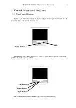
Page 9: ... at the lower center of the front panel as well as an LED for power status indication as shown below Also there are three control buttons i e Select Left and the Right on the front panel of the display as shown below And the associated functions of these keys are described as follows Power Button LED Left Button Select Button Right Button ...

Page 10: ... 3 2 Power LED The color of the power LED depends on the power status of the monitor When the LED color is continuously green it indicates the monitor is at normal operation state When the LED is in amber it indicates the monitor is at a power saving state 3 3 Tilting the Display CML155XW has a tilt feature that allows you to tilt the display back and forth or swivel the display left and right to ...

Page 11: ...onitor face down on a smooth surface covered by soft material to protect the panel faceplate 2 Back Cover Removal In Fig 4 1 remove 4 screws indicated as A from the four corner of the back cover Then remove the back cover 3 Metallic Cover Removal In Fig 4 2 remove 7 screws indicated as B from the back metallic cover Then remove the back metallic cover A Fig 4 1 B Fig 4 2 ...

Page 12: ... Remove 3 screws indicated as C from the inverter board and then remove the board carefully left side in Fig 4 3 c Remove 3 screws indicated as D from the audio board and then remove the board carefully d Remove 7 screws indicated as E from the main board connected with front cover Fig 4 3 5 Panel Removal a Remove 6 screws indicated as F from the front cover Fig 4 3 to remove the panel C Fig 4 3 D...

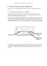
Page 13: ... with attached power cable and then connect the power cable to the power jack on the back of the display Plug the three prong power cord into a power outlet and plug the other end into the AC power adapter The three prong power cord is a shielded type and is provided as a safety precautions to ensure proper electrical grounding 3 Plug the D SUB 15 pin analog video signal cable or 20 pin DFP cable ...

Page 14: ...M D S Data2 13 T M D S Data3 2 T M D S Data2 14 5V Power 3 T M D S Data2 4 Shield 15 Ground for 5V 4 T M D S Data4 16 Hot Plug Detect 5 T M D S Data4 17 T M D S Data0 6 DDC Clock 18 T M D S Data0 7 DDC Data 19 T M D S Data0 5 Shield 8 No Connect 20 T M D S Data5 9 T M D S Data1 21 T M D S Data5 10 T M D S Data1 22 T M D S Clock Shield 11 T M D S Data1 3 Shield 23 T M D S Clock 12 T M D S Data3 24 ...

Page 15: ...e cable into the connector line it up carefully so that you don t bend the pins 5 2Connecting the monitor to an AV device 1 Plug the 4 pin s video signal cable or CVBS cable into the S video or CVBS Video Input port on the back of the display Connect the other end of the video cable into your AV s video port The assignment of the pins of the connector is as follows Audio 1 jack S video video input...

Page 16: ...5XW LCD Monitor Service Manual v1 0 15 Pin Assignment of 4 pin mini din connector 1 GND 3 Y_in 2 GND 4 C_in 2 Connect the audio cable to the speaker input jack on the back of the display labeled audio 2 Audio 2 jack ...

Page 17: ...ignals are of TTL level in amplitude and also protected by D016 D019 i e HSK120 The protected version of these two signals are buffered via I021 i e 74HCT14D and then fed into I011 1 at pin L2 and pin K1 III The signals terminated at P009 pin 12 and pin 15 are protected by D006 D009 i e HSK120 and then connected to I014 i e 24WC02 I014 stores the EDID data that serves for the purpose of plug and p...

Page 18: ...I002 i e HT7044A provide reset signal for I006 reset signal for I006 There is an interrupt signal comes from I011 5 pin R3 IRQn and is fed in to pin 14 of I006 INT0 The signal designated VGA_CON pin R4 of I011 5 is used for the determination of whether the analog signal video cable is connected to P009 or not And the signal designated DVI_CON pin L1 of I011 5 is used for the determination of wheth...

Page 19: ...ulated by I009 and I012 to provide 5V for the whole system And the 5V supply is fed into I016 I005 I007 and I008 to provide multiple 3 3V and 2 5V supplies The 12V also is fed into I001 to provide 5 0V independent for video decoder chip 6 2 Audio Board Circuit The circuit diagrams of audio board circuit is shown in Appendix C 6 3 Keyboard Circuit The circuit diagrams of keyboard circuit is shown i...

Page 20: ...he monitor please refer to troubleshooting flow chart in Appendix F 8 Proposed Repair Parts List For proposed repair parts list please refers to the Appendix G 9 Mechanical Disassembly For mechanical disassembly please refer to Appendix H 10 PCB Layout For PCB layout diagrams please refer to Appendix I ...

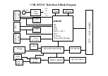
Page 21: ...Appendix A CML155XW Main Board Block Diagram ...

Page 22: ...DEO OSD SCALER 292 pin PBGA Package MICROCONTROLLER Power Supply Audio Amplifier Speaker Earphone INVERTER XTAL SDRAM ANALOG R G B EDID EPROM DVI EDID EPROM S Video and CVBS VIDEO DECODER EPROM Audio input 1 Audio input 2 AUDIO SELECT 12V DC 2 5V 3 3V 5V 12V TFT LCD PANEL ...

Page 23: ...Appendix B CML155XW Main Board Circuits ...

Page 24: ......

Page 25: ......

Page 26: ......

Page 27: ......

Page 28: ......

Page 29: ......

Page 30: ...Appendix C CML155XW Audio Board Circuit ...

Page 31: ......

Page 32: ...Appendix D CML155XW Key Board Circuit ...

Page 33: ......

Page 34: ...Appendix E CML155XW Inverter Board Circuit ...

Page 35: ......

Page 36: ...Appendix F CML155XW Troubleshooting Flow Charts ...

Page 37: ...End End The Voltage of L006 is 12V Replace F001 The Voltage of I012 1 is 12V Replace F002 The Voltage of L016 is 5V Replace I0012 D020 The Voltage at 40 of I006 is 5V Check I006 socket is loosened The Voltage of I016 2 is 3 3V Replace I016 The Voltage of I008 2 is 3 3V Replace I008 The Voltage of I005 2 is 2 5V Replace I005 The Voltage of I007 2 is 2 5V Replace I007 Yes Yes Yes Yes Yes Yes Yes Yes...

Page 38: ... cables at P010 P011 End Replace I011 GM5020 End End Are two flex cables attached firmly at the LCD panel connectors Replace V901 LCD panel End Are two flex cables attached firmly at P010 P011 Are the input waveforms of GM5020 normal Tighten two flex cables at P010 P011 Yes Yes Yes Yes No No No ...

Page 39: ...Appendix G CML155XW Repair Parts List ...

Page 40: ...THE UPDATED PARTS LIST FOR THIS MODEL IS AVAILABLE ON ESTA ...

Page 41: ...Appendix H CML155XW Mechanical Disassembly ...

Page 42: ......

Page 43: ...Appendix I CML155XW Printed Circuit Boards ...

Page 44: ......

Page 45: ......

Page 46: ......

Page 47: ......

Page 48: ... ITALY Tel 39 02 487861 Tel 39 02 38073415 Servizio Clienti Fax 39 02 48786381 2 Email customerservice italy hitachi eu com HITACHI Europe AB Box 77 S 164 94 Kista SWEDEN Tel 46 0 8 562 711 00 Fax 46 0 8 562 711 13 Email csgswe hitachi eu com HITACHI EUROPE S A S Lyon Office B P 45 69671 BRON CEDEX FRANCE Tel 04 72 14 29 70 Fax 04 72 14 29 99 Email france consommateur hitachi eu com HITACHI EUROPE...

Reviews: