6 MAINTENANCE
6-2
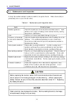
6.1 Maintenance and Inspection
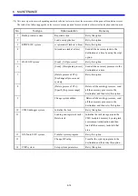
To keep the module running in optimal condition, it requires checks. Make checks daily or
periodically (twice a year or more often).
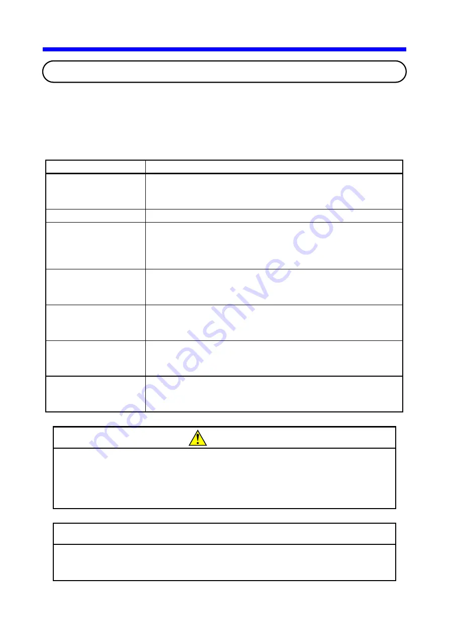
Table 6-1 Maintenance and Inspection Items
Item
Point to check
Module appearance
Check the module case for cracks, flaws and other defects. Such
defects can be a sign of breakage in the internal circuitry, causing
the system to malfunction.
LED
Check to see if the module ERR LED has not glowed.
Looseness of mounting
screws and terminal base
screws
Check the module and communications cable mounting screws for
tightness. Give additional tightening to screws found loose.
Loose screws could cause the system to malfunction and lead to
burnouts after heating.
Cable sheath condition
Check cable coverings for defects. A cable covering out of
position could cause the system to malfunction, incur electrical
shock hazards, or develop short circuits, resulting in burnouts.
Dust sticking condition
Check to see if the module has not caught dust. If dust is noticed,
remove it with a vacuum cleaner or other apparatus. Dust could
cause short circuits in its internal circuitry, resulting in burnouts.
Module replacement
Replacing the module without switching it off could cause damage
to its hardware and software. Before replacing the module, switch
it off first.
Connector condition
Connectors might have their characteristics degraded to cause
failures if their contacts catch dust or foreign matter. Cover
connectors out of use with the protective cap supplied.
CAUTION
Before replacing the module, switch it off to avoid electrical shock hazards and
also to prevent it from being damaged or malfunctioning. (When replacing the
battery module, be sure to follow the procedure described under “6.3 Replacing
the Battery Module.”)
NOTICE
Static electricity may damage the module. Before starting the work, discharge
all electrostatic charge from your body.
Summary of Contents for CMU LPQ520
Page 1: ......
Page 2: ......
Page 17: ...This Page Intentionally Left Blank ...
Page 19: ...This Page Intentionally Left Blank ...
Page 23: ...This Page Intentionally Left Blank ...
Page 28: ...v 6 4 Replacing the CMU Module 6 49 6 4 1 Replacing the module 6 49 6 5 Trouble Report 6 51 ...
Page 30: ...1 SPECIFICATIONS ...
Page 38: ...2 NAMES AND FUNCTIONS OF EACH PART ...
Page 43: ...This Page Intentionally Left Blank ...
Page 44: ...3 MOUNTING AND WIRING ...
Page 52: ...4 OPERATION ...
Page 85: ...This Page Intentionally Left Blank ...
Page 86: ...5 USER GUIDE ...
Page 101: ...This Page Intentionally Left Blank ...
Page 102: ...6 MAINTENANCE ...

