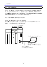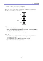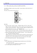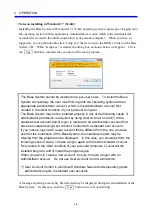
4 OPERATION
4-10
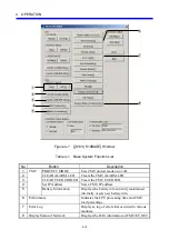
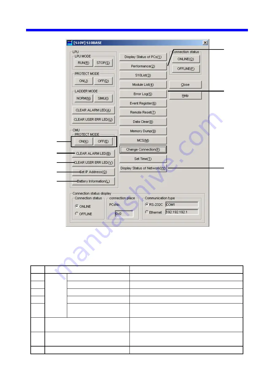
Figure 4-1 [[S10V] S10BASE] Window
Table 4-1 Base System Function List
No. Button
Description
1
CMU
PROTECT MODE
Sets CMU protect mode on or off.
2
CLEAR ALARM LED
Clears the CMU ALARM LED.
3
CLEAR USER ERR LED Clears the CMU USER LED.
4
Set IP Address
Sets a CMU IP address.
5
Battery Information
Displays the battery info currently maintained
internally or sets new battery info.
6
Performance
Indicates the LPU processing time and CMU
load percentage.
7
Error Log
Displays a log of errors that occurred in various
modules.
8
Display Status of Network
Displays the RAS information of CMU/ET.NET.
①
⑤
③
④
⑥
⑦
⑧
②
Summary of Contents for CMU LPQ520
Page 1: ......
Page 2: ......
Page 17: ...This Page Intentionally Left Blank ...
Page 19: ...This Page Intentionally Left Blank ...
Page 23: ...This Page Intentionally Left Blank ...
Page 28: ...v 6 4 Replacing the CMU Module 6 49 6 4 1 Replacing the module 6 49 6 5 Trouble Report 6 51 ...
Page 30: ...1 SPECIFICATIONS ...
Page 38: ...2 NAMES AND FUNCTIONS OF EACH PART ...
Page 43: ...This Page Intentionally Left Blank ...
Page 44: ...3 MOUNTING AND WIRING ...
Page 52: ...4 OPERATION ...
Page 85: ...This Page Intentionally Left Blank ...
Page 86: ...5 USER GUIDE ...
Page 101: ...This Page Intentionally Left Blank ...
Page 102: ...6 MAINTENANCE ...

