5 USER GUIDE
5-6
z
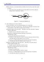
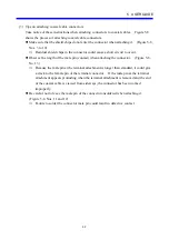
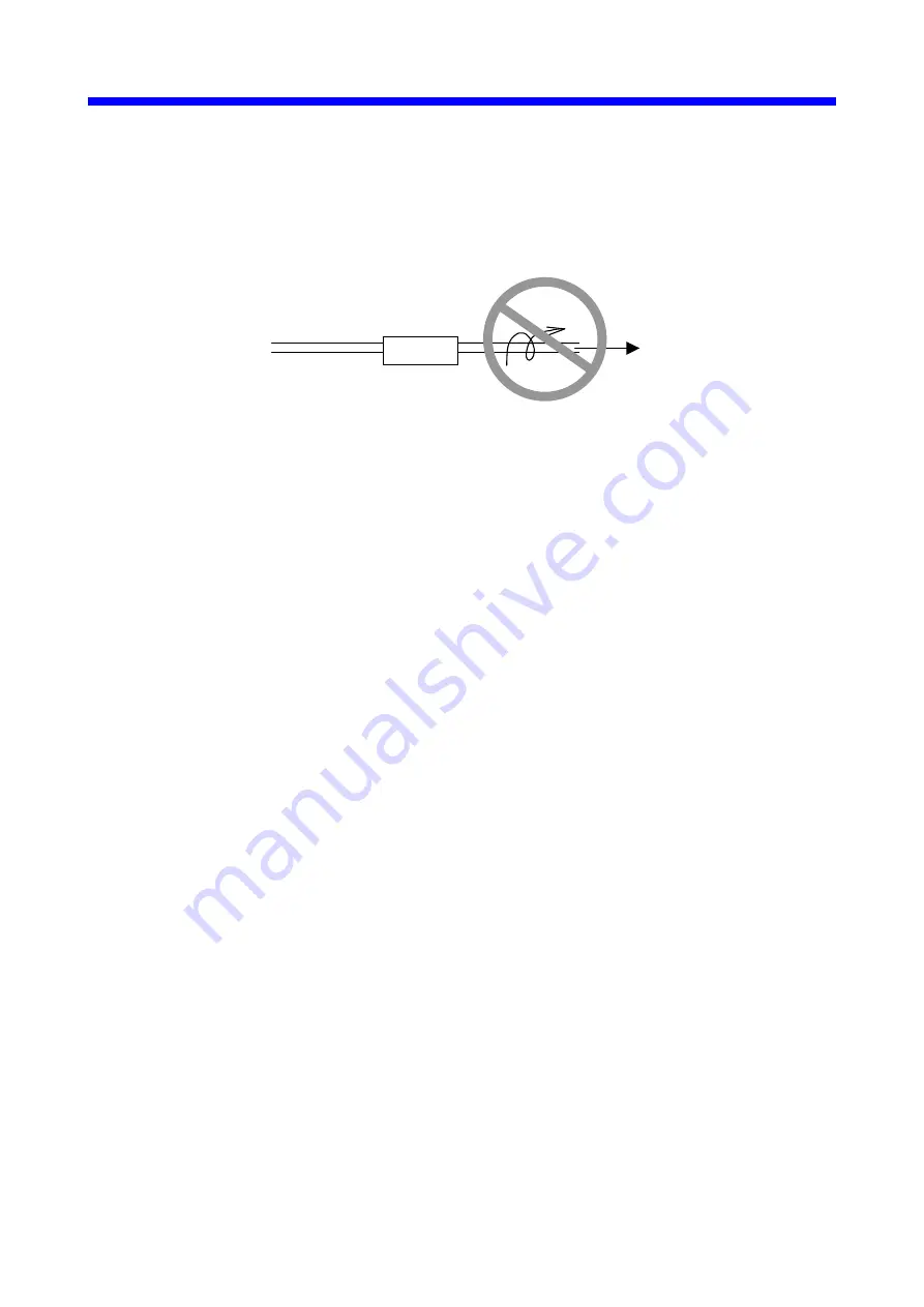
After a transceiver or terminator has been installed, do not twist the coaxial cable or pull
the clamp.
⇒
As the cable is twisted or pulled, the pin could grind the coaxial cable conductor,
causing defective contact upon vibration.
Transceiver
Coaxial cable
Twist
Pull
Figure 5-7 Transceiver Installation (2)
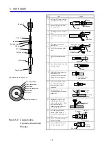
(2) Tips on clamping coaxial cable connectors
For more information, refer to the manual pertaining to the coaxial cable.
z
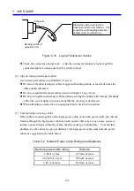
Tighten coaxial cable connectors firmly. Only about one-fourth turn of looseness could
result in defective contact after extended periods of vibration.
z
Tighten terminator connectors firmly. Remember to check the connectors for tightness
and then retighten them.
⇒
Slightest looseness could result in defective contact.
Instructions on retightening terminator connectors are given below.
<Retightening procedure>
①
Remove the rubber boot and connector cap.
②
Holding the coaxial connector securely by one hand, clamp the terminator with the
other hand and turn it firmly until it won’t go any more.
③
Finally, give additional tightening to the connector and check it for tightness.
④
After tightening, reattach the rubber boot and connector cap.
z
Tighten cable joints (relay connectors) firmly. Remember to check the joints for
tightness and then retighten them.
⇒
Slightest looseness could result in defective contact.
Instructions on retightening cable joints are given below.
<Retightening procedure>
①
Remove the connector cap.
②
Turn the connector ring firmly clockwise to clamp.
③
Finally, give additional tightening to the connector and check it for tightness.
④
After tightening, reattach the connector cap.
Summary of Contents for CMU LPQ520
Page 1: ......
Page 2: ......
Page 17: ...This Page Intentionally Left Blank ...
Page 19: ...This Page Intentionally Left Blank ...
Page 23: ...This Page Intentionally Left Blank ...
Page 28: ...v 6 4 Replacing the CMU Module 6 49 6 4 1 Replacing the module 6 49 6 5 Trouble Report 6 51 ...
Page 30: ...1 SPECIFICATIONS ...
Page 38: ...2 NAMES AND FUNCTIONS OF EACH PART ...
Page 43: ...This Page Intentionally Left Blank ...
Page 44: ...3 MOUNTING AND WIRING ...
Page 52: ...4 OPERATION ...
Page 85: ...This Page Intentionally Left Blank ...
Page 86: ...5 USER GUIDE ...
Page 101: ...This Page Intentionally Left Blank ...
Page 102: ...6 MAINTENANCE ...


