5 USER GUIDE
5-7
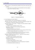
(3) Tips on attaching coaxial cable connectors
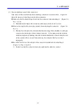
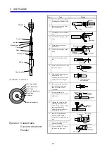
Take notice of these instructions when attaching connectors to coaxial cables. Figure 5-8
shows the process of attaching coaxial cable connectors.
z
Make sure that the shield chips do not enter the connector when attaching it. (Figure 5-8,
Nos. 3 to 10)
⇒
Residual shield chips in the connector could cause a short circuit to occur.
z
Observe the length of the male pin (contact) when attaching the connector. (Figure 5-8,
No. 13)
⇒
Because the male pin at the terminal attachment is longer than standard, it could give
a crack to the female pin of the terminal connector. If the male pin at the terminal
attachment appears protruding when the terminal attachment is removed and the end
of the coaxial cable is viewed from sideways, the connector has been worked
improperly.
z
Be careful not to leave the male pin of the connector unsoldered when attaching it.
(Figure 5-8, Nos. 11 and 12)
⇒
Failure to solder the connector male pin could result in defective contact.
Summary of Contents for CMU LPQ520
Page 1: ......
Page 2: ......
Page 17: ...This Page Intentionally Left Blank ...
Page 19: ...This Page Intentionally Left Blank ...
Page 23: ...This Page Intentionally Left Blank ...
Page 28: ...v 6 4 Replacing the CMU Module 6 49 6 4 1 Replacing the module 6 49 6 5 Trouble Report 6 51 ...
Page 30: ...1 SPECIFICATIONS ...
Page 38: ...2 NAMES AND FUNCTIONS OF EACH PART ...
Page 43: ...This Page Intentionally Left Blank ...
Page 44: ...3 MOUNTING AND WIRING ...
Page 52: ...4 OPERATION ...
Page 85: ...This Page Intentionally Left Blank ...
Page 86: ...5 USER GUIDE ...
Page 101: ...This Page Intentionally Left Blank ...
Page 102: ...6 MAINTENANCE ...

