5 USER GUIDE
5-9
(4) Tips on installing transceivers
z
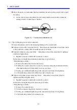
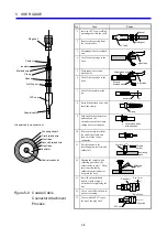
Be careful when driving transceiver pins not to let in coaxial cable shield chips.
⇒
Coaxial cable shield chips could the shield and conductor to be short-circuited to each
other.
z
Drive tap type transceiver pins straight.
⇒
If transceiver pins are driven slantwise, coaxial cable shield chips could the shield and
conductor to be short-circuited to each other. Further, the insulator at the pin tip
might crack causing a short circuit between the shield and conductor.
z
Do not install a transceiver at a bent section of a coaxial cable. Be sure to install one at a
straight section of a coaxial cable.
⇒
Obliquely driven pins could bring about phenomena similar to those described above.
Coaxial cable
Transceiver
Figure 5-9 Transceiver Installation (3)
z
When using a flame-retardant coaxial cable, use a connector type transceiver as a rule.
⇒
Flame-retardant coaxial cables more susceptible to the effects of external torsion than
regular standard coaxial cables because such force cause their internal conductor to
rotate slightly.
z
When using a flame-retardant coaxial cable for a tap type transceiver, camp the coaxial
and transceiver in the enclosure or else to protect the cable from external forces imparted
in rotating direction.
(5) Tips on laying transceiver cables
z
Before connecting or disconnecting a transceiver cable to or from a unit, switch it off.
z
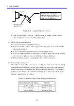
Allow a bending radius of at least 80 mm when both laying and finally clamping
transceiver cables.
z
Pay special attention to the bending of the connector attachment.
Summary of Contents for CMU LPQ520
Page 1: ......
Page 2: ......
Page 17: ...This Page Intentionally Left Blank ...
Page 19: ...This Page Intentionally Left Blank ...
Page 23: ...This Page Intentionally Left Blank ...
Page 28: ...v 6 4 Replacing the CMU Module 6 49 6 4 1 Replacing the module 6 49 6 5 Trouble Report 6 51 ...
Page 30: ...1 SPECIFICATIONS ...
Page 38: ...2 NAMES AND FUNCTIONS OF EACH PART ...
Page 43: ...This Page Intentionally Left Blank ...
Page 44: ...3 MOUNTING AND WIRING ...
Page 52: ...4 OPERATION ...
Page 85: ...This Page Intentionally Left Blank ...
Page 86: ...5 USER GUIDE ...
Page 101: ...This Page Intentionally Left Blank ...
Page 102: ...6 MAINTENANCE ...


