LAN port for connecting to the management LAN. There are two LEDs
next to the port.
¢
The LED on the left lights up when a link to the network is
established.
¢
The LED on the right flashes when the module is communicating via
the network.
#
The MGMT2 port cannot be used.
2
.
LID LED
This LED identifies the management LAN module. You can turn this LED
on or off from the Web console. You can use this LED to easily identify the
location of the target management LAN module.
3
.
MAINT port
This port is used exclusively by maintenance personnel when maintaining
the system unit. Users cannot use this port.
4
.
PWR/WRN LED
The lights of this LED signify the following statuses:
¢
Green light ON: The management LAN module is running correctly.
¢
Flashing green: A failure has occurred on the management LAN
module.
¢
OFF: The management LAN module is powered off.
Appearance of the switch module
The switch module has connectors for connecting the system unit to external
networks and indicators to show the status of the switch module itself. This
section describes the appearance, connectors, and indicators for each switch
module supported by the CB 2500.
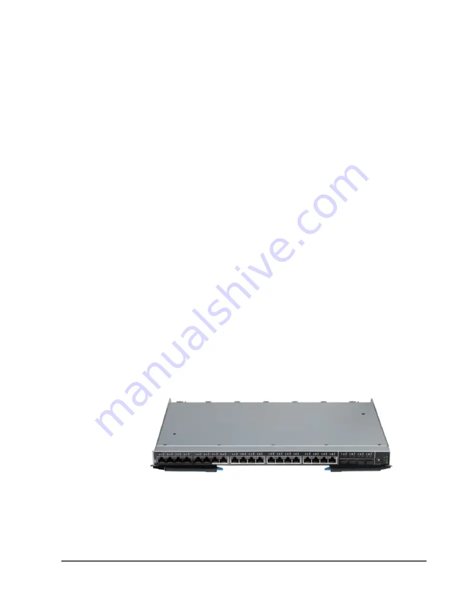
1/10Gb LAN switch module
The appearance of the 1/10Gb LAN switch module is shown below.
Figure 2-25 1/10Gb LAN switch module
The connectors and indicators of the 1/10Gb LAN switch module are
described below.
CB 2500 Appearance
2-21
Hitachi Compute Blade 2500 Series Getting Started Guide
Summary of Contents for Compute Blade 2500
Page 20: ...xx Preface Hitachi Compute Blade 2500 Series Getting Started Guide ...
Page 82: ...4 6 Stopping the CB 2500 Hitachi Compute Blade 2500 Series Getting Started Guide ...
Page 106: ...6 8 Troubleshooting Hitachi Compute Blade 2500 Series Getting Started Guide ...
Page 124: ...A 18 System Unit Specifications Hitachi Compute Blade 2500 Series Getting Started Guide ...
Page 152: ...Index 6 Hitachi Compute Blade 2500 Series Getting Started Guide ...
Page 153: ...Hitachi Compute Blade 2500 Series Getting Started Guide ...


