
viii
Preface
Hitachi Compute Rack 220S CRU Replacement Guide
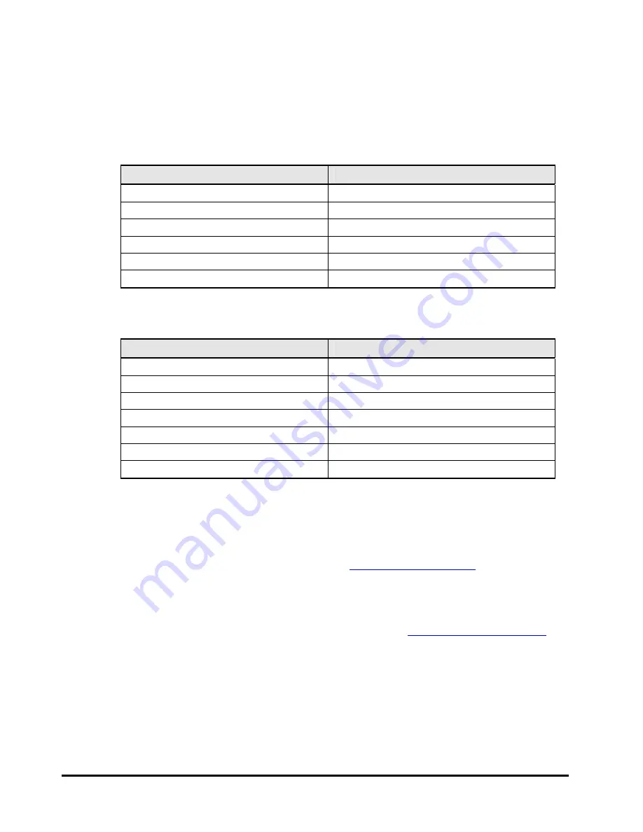
Convention for storage capacity values
Physical storage capacity values (for example, disk drive capacity) are calculated
based on the following values:
Physical capacity unit
Value
1 kilobyte (KB)
1,000 (10
3
) bytes
1 megabyte (MB)
1,000 KB or 1,000
2
bytes
1 gigabyte (GB)
1,000 MB or 1,000
3
bytes
1 terabyte (TB)
1,000 GB or 1,000
4
bytes
1 petabyte (PB)
1,000 TB or 1,000
5
bytes
1 exabyte (EB)
1,000 PB or 1,000
6
bytes
Logical storage capacity values (for example, logical device capacity) are
calculated based on the following values:
Logical capacity unit
Value
1 block
512 bytes
1 KB
1,024 (2
10
) bytes
1 MB
1,024 KB or 1,024
2
bytes
1 GB
1,024 MB or 1,024
3
bytes
1 TB
1,024 GB or 1,024
4
bytes
1 PB
1,024 TB or 1,024
5
bytes
1 EB
1,024 PB or 1,024
6
bytes
Getting Help
The Hitachi Data Systems customer support staff is available 24 hours a day,
seven days a week. If you need technical support log on to the Hitachi Data
Systems Portal for contact information:
Comments
Please send us your cInclude the document title and number including the revision level (for example,
-07), and refer to specific sections and paragraphs whenever possible. All
comments become the property of Hitachi Data Systems Corporation.
Thank you!


