ModBus Data Listing
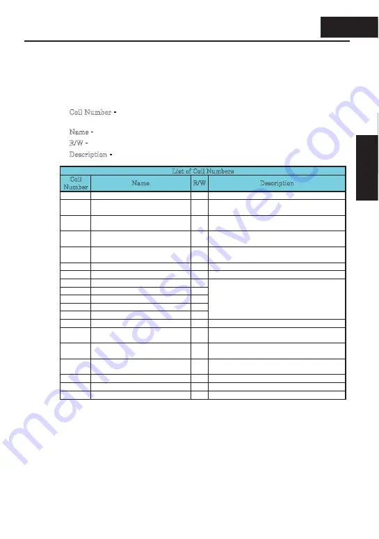
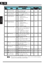
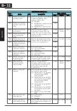
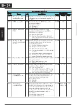
ModBus Coil List
The following tables list the primary coils for the inverter interface to the network. The
table legend is given below.
x
Coil Number - The network
register address offset for the coil. The coil data is a
single bit (binary) value.
x
Name - The functional name of the coil
x
R/W - The read-only (R) or read-write (R/W) access permitted to the inverter data
x
Description - The meaning of each of the states of the coils
List of Coil Numbers
Coil
Number
Name
R/W
Description
0000h
(Reserved)
R
0001h
Run command
R/W
0…Stop
1…Run (enable when A003=03)
0002h
FW/RV command
R/W
0…RV
1…FW (enable when A003=03)
0003h
External trip (EXT)
R/W
0…No trip event
1…Trip occurred
0004h
Trip reset (RS)
R/W
0…No reset condition
1…Reset
0005h
(Reserved)
R
0006h
(Reserved)
R
0007h
Intelligent input terminal 1
R/W
0008h
Intelligent input terminal 2
R/W
0009h
Intelligent input terminal 3
R/W
000Ah
Intelligent input terminal 4
R/W
000Bh
Intelligent input terminal 5
R/W
0…OFF *1
1…ON
000Dh
(Not used)
000Eh
Run/Stop status
R
0…Stop (corresponds to D003 monitor)
1…Run
000Fh
FW/RV status
R
0…FW
1…RV
0010h
Inverter ready
R
0…Not ready
1…Ready
0011h
(Reserved)
R
0012h
(Reserved)
R
0013h
(Reserved)
R
B
19
Appe
ndix B
B
−
19
Appendix B


