background image

--- 12 ---

7. PRECAUTIONS IN SALES PROMOTION

7-1. Safety Instructions

In the interest of promoting the safest and most efficient use of the Model CR 18DMR by all our customers, it is

very important that at the time of sale, the salesperson carefully ensures that the buyer seriously recognizes the

importance of the contents of the Handling Instructions, and fully understands the meaning of the precautions

listed on the Caution Plate and Name Plate attached to each tool.

A. Handling Instructions

Salespersons must be thoroughly familiar with the contents of the Handling Instructions in order to give pertinent

advice to the customer.  In particular, they must have a thorough understanding of the precautions in the use of

the cordless (battery charger type) electric power tools which are different from those of ordinary electric power

tools.

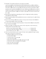
(1) Before use, ensure that the unit is fully charged.

New units are not fully charged.  Even if the units were fully charged at the factory, long periods without use,

such as during shipping, cause the storage battery to lose its charge.  Customers must be instructed to fully

charge the unit prior to use.

(2) When charging storage batteries, use only the exclusive Model UC 24YFA Charger provided with the tool.

Because of the designed rapid-charging feature (about one hour), use of other battery chargers is hazardous.

(3) Ensure the power source voltage is the same as that indicated on the Name Plate of the charger.  Use of any

other power source (DC outlet, fuel powered generator, etc.) will cause the charger to overheat and burnt out.

(4) Do not use any voltage increasing equipment (transformer etc.) between the power source and the charger.

If the charger is used with voltage over and above that indicated on the unit, it will not function properly.

(5) Conduct battery charging at an ambient temperature range of 0 

û

C --- 40 

û

C (32 

û

F --- 104 

û

F).

Special temperature sensitive devices are employed in the charger to permit rapid charging.  Ensure that

customers are instructed to use the charger at the indicated ambient temperature range.  At temperature over

40 

û

C (104 

û

F), the storage battery cannot be sufficiently charged.  The optimum temperature range is 20 

û

C ---

25 

û

C (68 

û

F --- 77 

û

F).

(6) The battery charger should not be used continuously.

At high ambient temperature, if over three storage batteries are charged in succession, the temperature of the

coils on the transformer will rise.  After charging one battery, please charge the next battery after about a

fifteen-minute inerval.

(7) Do not insert foreign objects into the air vents on the charger

The charger case is equipped with air vents to protect the internal electronic components from overheating.

Caution the customer not to allow foreign materials, such as metallic or inflammable objects, to be dropped or

inserted into the air vents.  This could cause electrical shock, fire, or other serious hazards.

(8) Do not attempt to disassemble the storage battery or the charger.

Special devices, such as a thermistor, are built into the storage battery and charger to permit rapid charging.

Incorrect parts replacement and/or wiring will cause malfunctions which could result in fire or other hazards.

Instruct the customer to bring these units to an authorized service center in the event repair or replacement is

necessary.

Summary of Contents for CR 18DMR

Page 1: ...TECHNICAL DATA AND SERVICE MANUAL CORDLESS RECIPROCATING SAW CR 18DMR SPECIFICATIONS AND PARTS ARE SUBJECT TO CHANGE FOR IMPROVEMENT LIST No G824 June 2005 C MODEL CR 18DMR Hitachi Power Tools ...

Page 2: ...ol s is are used in the place of company name s and model name s of our competitor s The symbol s utilized here is are as follows Symbols Utilized Competitors Company Name Model Name MAKITA JR180DWD M RIDGID R844 R DEWALT DC385 D BOSCH 1644 24 B MILWAUKEE 6514 20 W ...

Page 3: ...cation Comparisons 18 V cordless reciprocating saw 9 6 2 Working Performance per Single Charge reference only 10 7 PRECAUTIONS IN SALES PROMOTION 12 7 1 Safety Instructions 12 7 2 Inherent Drawbacks of Cordless Reciprocating Saw Requiring Particular Attention During Sales Promotion 14 7 3 Front Cover 15 8 REPAIR GUIDE 15 8 1 Precautions in Disassembly and Reassembly 15 9 STANDARD REPAIR TIME UNIT ...

Page 4: ...for ease of operation In addition the Model CR 18DMR is equipped with the high strength components equivalent to the 24 V product Model CR 24DV 3 APPLICATIONS Cutting metal wood plastics etc 4 SELLING POINTS Saw blade can be mounted in either direction upward or downward Nonskid and comfortable soft grip handle Easy to operate maintain tool less blade detachable mechanism The Model CR 18DMR is ser...

Page 5: ...blades can be easily mounted and removed just by pressing the lever Easy to maintain The tool less blade detachable mechanism can be disassembled and reassembled without removing the front cover How to mount a saw blade a Push the lever in the direction of the arrow marked on the lever 1 2 b Insert the saw blade all the way into the small slit of the plunger tip with the lever pushing c Release th...

Page 6: ...e mount with a brush to ensure that the tool less blade detachable mechanism can function smoothly In addition to the regular maintenance perform the following effective maintenance occasionally Cleaning the inside of the tool less blade detachable mechanism Pull the rubber cap provided on the lever in the direction of an arrow mark shown below Then the rubber cap can be removed from the lever eas...

Page 7: ...lade is apt to come off if the blade hole is worn out Replace the saw blade with new one If the new saw blade comes off even after replacement the holder pin may be worn out Replace the holder pin with new one Front cover Fixing bolt Blade holder Blade hole Refer to the Handling Instructions for detailed information about saw blade replacement 2 Saw blade can be mounted in either direction upward ...

Page 8: ... brush on the contact portion outside the brush tube Nail of carbon brush Protrusion of carbon brush Contact portion outside brush tube Fig 2 4 Lock off button The lock off button is adopted to avoid the switch from unintentionally being turned on during storage or carrying When using 5 Convenient switch trigger shape for easy operation The switch trigger is large enough to operate with two finger...

Page 9: ...mperature range 0ûC 40ûC 32ûF 104ûF The maximum allowable temperature of the type EB 1820L battery is 60ûC 140ûF and the type EB 1826HL or EB 1830HL battery is 45ûC 113ûF Indication method of battery charging function Sealed cylinder nickel cadmium storage battery Nominal voltage DC 18V Nominal life Charging discharging approximately 1 000 times in case of Model UC 24YFA Nominal capacity 2 0 Ah D ...

Page 10: ...sition of each blade Select appropriate blades by referring to Tables 1 and 3 below Table 1 HCS blades For cutting and roughing lumber Blade No Uses Thickness mm For cutting steel pipes less than 100 mm 4 in outer diameter 2 5 6 3 32 1 4 No 1 No 3 No 96 No 95 No 9 No 8 No 5 No 4 No 2 For cutting steel pipes less than 30 mm 1 3 16 in outer diameter For cutting steel pipes less than 30 mm 1 3 16 in ...

Page 11: ...104 131 132 Blade No Uses Thickness mm For cutting steel and stainless pipes less than 60 mm 2 3 8 in outer diameter No 101 For cutting steel and stainless pipes less than 60 mm 2 3 8 in outer diameter No 103 For cutting steel and stainless pipes less than 100 mm 4 in outer diameter No 102 For cutting steel and stainless pipes less than 100 mm 4 in outer diameter No 104 For cutting steel and stain...

Page 12: ... 9 6 COMPARISONS WITH SIMILAR PRODUCTS 6 1 Specification Comparisons 18 V cordless reciprocating saw ...

Page 13: ...r 48 6 mm 1 91 thickness 3 5 mm 0 14 HITACHI genuine blade No 103 for cutting steel pipes Fig 4 Fig 5 Cutting wood Pressing force about 5 kgf 11 lbs HITACHI genuine blade No 121 for cutting wood Pressing force about 5 kgf 11 lbs Thickness Width Lumber SPF 2 x 10 38 mm 1 50 in thickness and 235 mm 9 25 in width ...

Page 14: ...R The following test data should be used for reference purposes only since the cutting speed and the working capacity may vary depending on the operating conditions such as the pressing force type of blades materials etc ...

Page 15: ...verheat and burnt out 4 Do not use any voltage increasing equipment transformer etc between the power source and the charger If the charger is used with voltage over and above that indicated on the unit it will not function properly 5 Conduct battery charging at an ambient temperature range of 0 ûC 40 ûC 32 ûF 104 ûF Special temperature sensitive devices are employed in the charger to permit rapid...

Page 16: ...B 1820L EB 1826HL and EB 1830HL batteries CAUTION Read thoroughly HANDLING INSTRUCTIONS before use Do not disassemble nor throw into fire For Europe CAUTION For safe operation see instruction manual Use HITACHI charger UC 24YFA for recharging For the U S A and Canada CAUTION Read thoroughly HANDLING INSTRUCTIONS before use WARNING To reduce the risk of injury user must read and understand instruct...

Page 17: ... 0 Ah 2 6 Ah and 3 0 Ah the actual capacity may vary within 10 of that value depending on the ambient temperature during use and charging and the number of times the batteries have been recharged It should be noted that other factors which may have a bearing on the amount of work possible per charge are the working conditions ambient temperature type and moisture content of the workpiece sharpness...

Page 18: ...sher M4 x 12 17 and the Cover Plate 18 and pull out the Front Cover 19 Remove the four Hex Socket Hd Bolts W Sp Washer M5 x 16 9 from the Upper Cover 8 Pull the Upper Cover 8 straight and remove it 2 Removal of the Plunger 3 from the Upper Cover 8 Remove the two Seal Lock Hex Socket Flat Hd Bolts M5 x 12 28 from the Connector 33 If the Seal Lock Hex Socket Flat Hd Bolts M5 x 12 28 are too tight he...

Page 19: ...21 and Ball Bearing 6901ZZCMPS2L 22 8 Disassembly of the blade mounting section Slide the Cap 11 made of rubber out of Lever A 12 with fingers horizontally Remove the Special Bolt M4 10 Then Blade Holder A 1 Lever A 12 Spring D 13 Holder Pin B 14 and Spring B 15 can be removed from the Plunger 3 At this time be careful not to lose Spring B 15 9 Disassembly of the housing section Remove the seven T...

Page 20: ...lder A 1 Keeping this state insert the tip of Plunger 3 into Blade Holder A 1 At this time fit Spring D 13 in the groove of the Plunger 3 securely Tighten the Special Bolt M4 10 and Nut M4 Black 2 at the specified torque Push the Cap 11 to Lever A 12 from the side so that the arrow mark on the Cap 11 points downward At this time check that there is no gap between the Cap 11 and Blade Holder A 1 Be...

Page 21: ...he Upper Cover 8 to the Gear Cover Ass y 27 5 Align the notch of the Magnet 43 with the protrusion of housing A side of Housing A B Set 46 when mounting the Magnet 43 to Housing A B Set 46 6 Do not pinch internal wires between the matching surfaces of Housing A B Set 46 when storing internal wires in Housing A B Set 46 7 Adhesives are applied to the following screws and bolts When reusing these sc...

Page 22: ...0 5 to 0 8 N m 5 to 8 kgf cm Machine Screws W Sp Washer M4 x 12 17 1 8 0 4 N m 18 4 kgf cm Seal Lock Flat Hd Screw M4 x 12 20 1 8 0 4 N m 18 4 kgf cm Hex Socket Hd Bolt W Sp Washer M5 x 16 9 8 8 1 0 N m 90 10 kgf cm Seal Lock Hex Socket Flat Hd Bolt M5 x 12 28 5 4 0 5 N m 55 5 kgf cm Nylock Hex Socket Flat Hd Bolt M6 x 16 29 11 8 1 0 N m 120 10 kgf cm Nut M4 2 2 9 0 5 N m 30 5 kgf cm ...

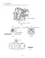
Page 23: ... 20 Fig 11 Fig 12 Fig 13 Wiring diagram Internal wire Red 8 1 3 Wiring diagram Be sure to perform wiring connections as indicated in Figs 12 13 14 and 15 Fig 14 ...

Page 24: ... Control Switch Terminal Piece Set Base Front Cover Armature Ass y Ball Bearing 608VV Ball Bearing 6001VV Gear Cover Ass y Spindle Ball Bearing 6901ZZ Gear Needle Roller Connecting Piece A Connector Connector Holder Blade Holder A Plunger O ring Upper Cover Seal Packing General Assembly Housing A B Set Magnet ...

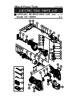
Page 25: ...IPROCATING SAW Model CR 18DMR 2005 4 15 E1 Hitachi Power Tools 1 2 3 4 5 6 7 8 9 7 10 11 12 13 14 15 16 17 18 19 20 21 22 23 24 25 26 27 28 29 30 31 32 33 34 35 36 37 38 39 40 17 41 42 43 44 45 47 48 46 49 50 51 52 53 54 55 56 57 58 501 502 503 504 505 ...

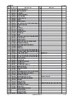
Page 26: ... 789 METAL B 1 25 996 399 HEX SOCKET HD BOLT W FLANGE M5X12 1 26 986 011 TAPPING SCREW W SP WASHER D5X30 4 27 319 844 GEAR COVER ASS Y 1 INCLUD 24 28 319 875 SEAL LOCK HEX SOCKET FLAT HD BOLT M5X12 2 29 319 851 NYLOCK HEX SOCKET FLAT HD BOLT M6X16 1 30 319 856 SEAL PACKING 1 31 319 874 PACKING B 1 32 983 567 CONNECTOR HOLDER 1 33 996 405 CONNECTOR 1 34 983 541 CONNECTING PIECE A 1 35 324 470 NEEDL...

Page 27: ... CONTROL SWITCH 1 54 NAME PLATE 1 55 302 086 TAPPING SCREW W FLANGE D4X20 BLACK 8 56 319 812 HEAT SINK 1 57 993 963 MACHINE SCREW W WASHERS M3X12 1 58 322 880 BATTERY EB 1820L W ENGLISH N P 2 58 322 878 BATTERY EB 1826HL W ENGLISH N P 2 58 322 877 BATTERY EB 1830HL W ENGLISH N P 2 58 322 876 BATTERY EB 1830HL W ENGLISH N P 2 FOR TPE ...

Page 28: ...1 605 958 185 SABER SAW BLADES NO 5 5 PCS 1 606 958 188 SABER SAW BLADES NO 8 5 PCS 1 607 996 427 SABER SAW BLADES NO 9 3 PCS 1 608 959 799 SABER SAW BLADES NO 95 3 PCS 1 609 959 800 SABER SAW BLADES NO 96 3 PCS 1 610 318 611 SABER SAW BLADES NO 101 150L P 10 5 PCS 1 611 318 612 SABER SAW BLADES NO 102 228L P 10 5 PCS 1 612 318 614 SABER SAW BLADES NO 104 228L P 14 5 PCS 1 613 318 615 SABER SAW BL...

Page 29: ......
Reviews: