


9
○
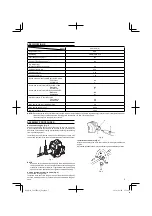
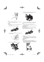
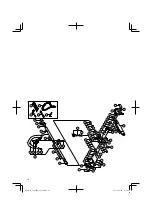
Spectator and fellow workers must be warned, and children and
animals prevented from coming nearer than 15M while the pole
saw is in use. (
Fig. 23
)
15 m
Fig. 23
○
Avoid all power lines. This unit is not insulated against electrical
current.
○
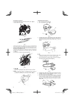
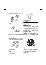
Always wear head protection with full face shield to help protect
against falling branches and debris. (
Fig. 24
)
Fig. 24
Pruning techniques
This attachment is designed for pruning small limbs and branches up
to 200 mm in diameter.
Follow these tips for successful operation.
○
Plan cut carefully. Check direction branch will fall.
○
Long branches should be removed in several pieces.
○
Do not stand directly beneath branch being cut.
○
When ready to cut: Hold "front cutting guide" against branch.
This will prevent whipping of the branch. DO NOT use back and
forth sawing action. (
Fig. 24
)
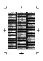
○
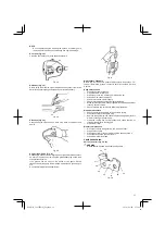
Look out for branch immediately behind the branch being cut, If
blade hits rear branch damage to blade may occur. (
Fig. 25
)
Fig. 25
○
Accelerate to full throttle.
○
Apply a light cutting pressure.
○
Ease cutting pressure when nearing end of cut to maintain
control.
○
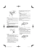
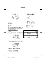
When pruning a limb 100 mm diameter or larger, cut as follows:
(
Fig. 26
)
1. Undercut 1/4 limb diameter near tree trunk.
2. Finish top cut slightly farther out on limb.
3. Flush cut stub at trunk.
1
2
Fig. 26
○
DO NOT use for felling or bucking.
MAINTENANCE
MAINTENANCE, REPLACEMENT OR REPAIR OF THE EMISSION
CONTROL DEVICES AND SYSTEMS MAY BE PERFORMED
BY ANY NON-ROAD ENGINE REPAIR ESTABLISHMENT OR
INDIVIDUAL.
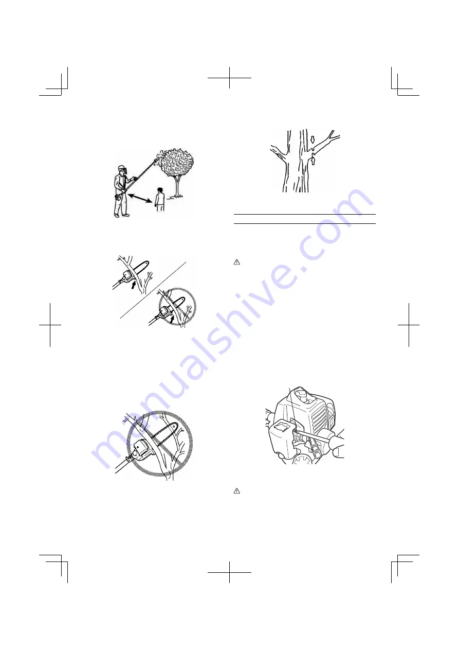
Carburetor adjustment (Fig. 27)
WARNING
○
The cutting attachment may be spinning during carburetor
adjustments.
○
Never start the engine without the complete clutch cover and
tube assembled! Otherwise the clutch can come loose and
cause personal injuries.
In the carburetor, fuel is mixed with air. When the engine is test run at
the factory, the carburetor is basically adjusted. A further adjustment
may be required, according to climate and altitude. The carburetor
has one adjustment possibility:
T = Idle speed adjustment screw.
Idle speed adjustment (T)
Check that the air
fi
lter is clean. When the idle speed is correct, the
cutting attachment will not rotate. If adjustment is required, close
(clockwise) the T-screw, with the engine running, until the cutting
attachment starts to rotate. Open (counter-clockwise) the screw
until the cutting attachment stops. You have reached the correct idle
speed when the engine runs smoothly in all positions well below the
rpm when the cutting attachment starts to rotate.
If the cutting attachment still rotates after idle speed adjustment,
contact your Hitachi Authorized Service Centers.
T
Fig. 27
NOTE
Standard Idle rpm is 2500 – 3000 min
-1
.
WARNING
When the engine is idling the cutting attachment must under no
circumstances rotate.
Air
fi
lter (Fig. 28)
The air
fi
lter must be cleaned from dust and dirt in order to avoid:
○
Carburetor
malfunctions
○
Starting
problems
○
Engine power reduction
000Book̲CS27EPA(S)̲Eng.indb 9
000Book̲CS27EPA(S)̲Eng.indb 9
2014/06/04 15:14:27
2014/06/04 15:14:27