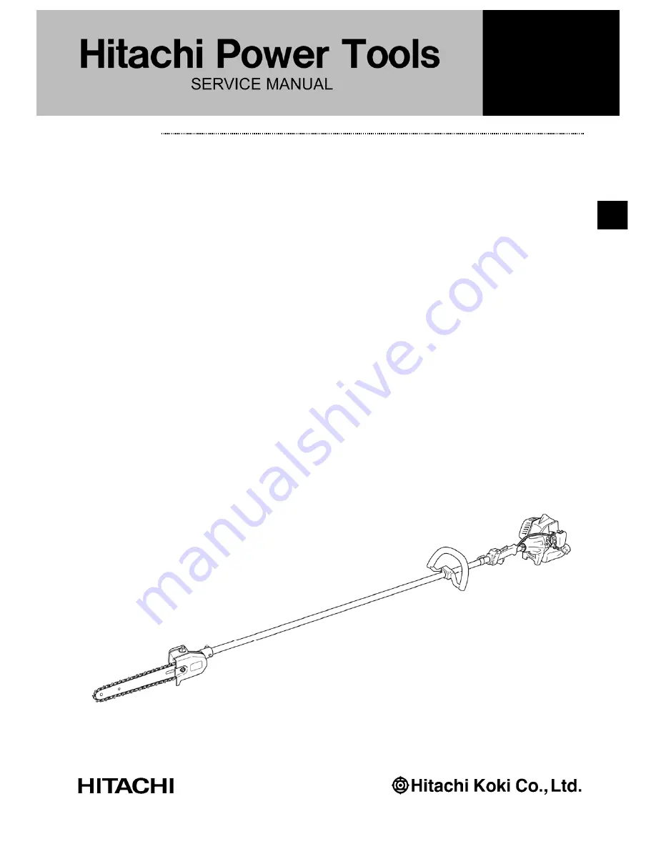
background image

PRODUCT NAME 

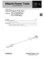
Hitachi Engine Pole Saw 

Models

CS 27EPAP(S) 

      CS 27EPA(S) 

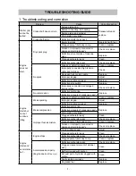
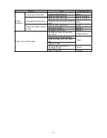
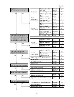
TROUBLESHOOTING GUIDE ---------------------------------------------------------------------------------------------- 1 

1. Troubleshooting and correction ------------------------------------------------------------------------------- 1 

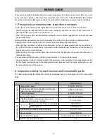
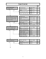
REPAIR GUIDE ----------------------------------------------------------------------------------------------------------------- 3

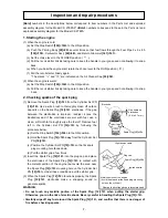
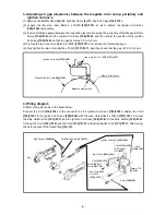
1. Precaution on maintenance, inspection and repair ------------------------------------------------------ 3 

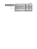
2. Inspection criteria for each section and consumable parts -------------------------------------------- 3

CONTENTS  

Page

LIST Nos.   
CS 27EPAP: F021 
CS 27EPA:  F020 
Sep. 2012

International Sales Division 

Summary of Contents for CS 27EPA(S)

Page 1: ...LESHOOTING GUIDE 1 1 Troubleshooting and correction 1 REPAIR GUIDE 3 1 Precaution on maintenance inspection and repair 3 2 Inspection criteria for each section and consumable parts 3 CONTENTS Page LIST Nos CS 27EPAP F021 CS 27EPA F020 Sep 2012 International Sales Division 䠟 ...

Page 2: ...ires Check or replace No compression Defective piston ring Replace Defective oil seals of crank case ass y Engine starts but cannot continue idling Weak sparking Stained or defective spark plug Clean or replace Improper air gap Adjust Defective ignition coil ass y Replace Weak compression Defective piston ring Replace Defective oil seals of crank case ass y Worn piston or cylinder Improper fuel ai...

Page 3: ...er element of cleaner ass y Clean Saw chain rotates at idling speed Improper idling adjustment Adjust Worn clutch section Replace Degraded clutch spring Replace Chain oil is not discharged Insufficient amount of chain oil in the oil tank Supply chain oil Clogged chain oil discharge port Clean Clogged oil filler port on the chain bar Clogged oil filter Poor adjustment of chain oil discharge amount ...

Page 4: ... serious burn injury or electric shock Before starting the engine with the saw chain and the chain bar attached make sure that there are no other people nearby Ensure proper ventilation when performing repair indoors or in other protected areas Upon completion of repair carefully confirm that all screws nuts and bolts are properly tightened the throttle trigger returns properly to the idling posit...

Page 5: ...ive spark plug Clean or replace 7 Improperly connected high tension cable and terminal Inspect 8 9 Damaged high tension cable Replace 8 9 Improper air gap Adjust 8 Defective ignition coil ass y Replace 8 Defective stop switch Replace 8 9 Improperly connected or damaged internal wires Inspect or replace 8 9 Defective piston ring Clean or replace 12 13 Worn piston Replace 12 13 Defective oil seals o...

Page 6: ...spect or replace 10 Clogged pump filter body comp Clean 9 Improper fuel air mixture Defective carburetor ass y Inspect or replace 10 Clogged cleaner element of cleaner ass y Clean 9 Carbon clogged in muffler cylinder or Exhaust vents Clean 9 Faulty ignition coil ass y Replace 8 Degraded fuel Replace ʊ Clogged carburetor ass y Clean 10 Defective carburetor ass y Inspect or replace 10 Defective carb...

Page 7: ...Supply oil ʊ Clogged chain oil discharge port Clean 15 16 17 Clogged chain bar oil feed port Clean 15 16 17 Clogged oil filter Clean 15 16 17 Poorly adjusted discharge amount of chain oil Adjust 15 16 17 Crack of fuel pipes Replace 15 16 17 Is chain oil discharged No ...

Page 8: ...ot allowing it to snap back 2 Checking sparks of the spark plug 1 Remove the Spark Plug 12 12 from the Cylinder Set PN 19 19 Use a wire brush to thoroughly clean off carbon deposits on the Spark Plug 12 12 electrodes If the gap between the electrodes is improper readjust it see the illustration and if the electrodes are wet with fuel use a clean soft cloth to thoroughly wipe the fuel off Remove fu...

Page 9: ...e two Hex Hole Bolts 4 x 18WS 127 127 and remove the thickness gauge 5 Fully tighten the Hex Hole Bolts 4 x 18WS 127 127 and then check that the gap is 0 3 to 0 4 mm 4 Wiring diagram Perform wiring as shown in the figure below Connect the Cord 134 134 to the connector on the Ignition Coil Ass y 128 128 Fasten the Cord 135 135 to the Ignition Coil Ass y 128 128 with the Hex Hole Bolts 4 x 18WS 127 ...

Page 10: ...Cylinder Set PN 19 19 with the Piston Set PN 55 54 and then scrape off carbon accumulated at the exhaust port of the Cylinder Set PN 19 19 NOTE Do not scratch the Piston Set PN 55 54 7 Cleaning the cleaner element Open the Air Cleaner Cap 53 52 of the Air Filter Ass y 54 53 Remove the Cleaner Element 52 51 and clean it with compressed air If the Cleaner Element 52 51 is heavily stained clean it wi...

Page 11: ...ation or wear is found replace the Carburetor Ass y 48 48 or its faulty parts 2 Adjusting the Carburetor Ass y 48 48 Adjust the throttle valve opening for idling by turning the idle adjust screw To increase the engine speed turn it clockwise To reduce the engine speed turn it counterclockwise If the Saw Chain 225 225 rotates during idling reduce the engine speed so that the Saw Chain 225 225 does ...

Page 12: ...or insulator set Open the Air Cleaner Cap 53 52 of the Air Filter Ass y 54 53 loosen the two Plus Screws 5 x 60WS 50 50 and then remove the Air Filter Ass y 54 53 Carburetor Ass y 48 48 Carburetor Gasket 47 47 Throttle Wire Fixing Plate 46 46 and Carburetor Packing 45 45 together Loosen the two Seal Lock Hex Socket Bolts W Washers M5 44 44 and then remove the Carburetor Insulator Set PN 43 43 and ...

Page 13: ...e the two Cir Clips 57 56 by using long nose pliers lightly strike the Piston Pin 58 57 to remove it and then remove the Piston Set PN 55 54 Remove the Piston Ring 56 55 while expanding the closed gap of the ring Because the Piston Ring 56 55 is a cast iron part do not forcibly expand it Doing so may break the ring 13 Removing the crank case ass y starter side and driving side Loosen the four Hex ...

Page 14: ...erwise the Piston Ring 56 55 may be easily damaged NOTE If you use a new Crank Case Ass y 61 60 unnecessary portion of the Crank Case Packing 62 61 must be cut off along the Cylinder Set PN 19 19 matching surface after assembling the Crank Case Ass y 61 60 4 Reassembling the magneto rotor comp Mount the Magneto Rotor Comp 136 136 while aligning the integral key at the center hole of the Magneto Ro...

Page 15: ... by hand heat the Case 220 220 and then strike with a rubber hammer in order to pull out the Pinion 192 192 Ball Bearing 609 193 193 Ball Bearing 609Z ST 194 194 and Stop Ring C 9 Outer 195 195 as a complete set NOTE Be sure to wear thick cotton gloves or similar protection when holding the heated Case 220 220 so as to avoid burning your hands Also be careful not to deform the Case 220 220 6 Use a...

Page 16: ...ippon Oil Energy to the inner and outer peripheries of the O ring 182 182 and then attach the O ring 182 182 to the Oil Pump Comp 181 181 Apply Primary Oil SAE30 JX Nippon Oil Energy to the shaft of the Oil Pump Piston Comp 186 186 and Turbine Oil 56 JX Nippon Oil Energy to the inner and outer peripheries of the O ring 1 4 183 183 Pass the Oil Pump Spring 185 185 and the Washer 2 184 184 through t...

Page 17: ...5 5 mm dia hole of the Main Pipe Comp 170 170 securely tighten the Hex Hole Bolt 5 x 10 198 198 so as to prevent removal of the Case 220 220 from the Main Pipe Comp 170 170 and then tighten the Hex Hole Bolt 5 x 22 S 190 190 to fix the Main Pipe Comp 170 170 and the Case 220 220 in place Install the Chain Bar 226 226 onto the Chain Bar Tightening Bolt 222 222 then push it toward the Sprocket Comp ...

Page 18: ...ecurely tighten the Chain Bar Clamp Nut 227 227 with the Combi Box Spanner 13 x 19 Minus 501 501 The new Saw Chain 225 225 will stretch so adjust the Saw Chain 225 225 after a few cuts and watch tension of the Saw Chain 225 225 carefully for the first half hour of cutting CAUTION When the chain is excessively tightened the bar and chain will be damaged rapidly Conversely when the chain is excessiv...

Page 19: ... 5 5 mm 2 0 to 3 0 21 to 30 Recoil starter ass y Screw 4 x 22 PS 3 3 4 mm 2 5 to 3 5 26 to 35 Tank ass y Flange Bolt 145 145 5 mm 4 0 to 5 0 41 to 51 Bolt W Flange L27 8 148 148 5 mm 4 0 to 5 0 41 to 51 Handle A B Tapping Screw D4 101 101 4 mm 1 5 to 2 4 16 to 23 Loop handle ass y Tapping Screw 5 x 20 165 165 5 mm 2 4 to 3 4 25 to 35 Main pipe Hex Hole Bolt M5 x 12 S 111 111 5 mm 3 5 to 4 5 36 to ...

Page 20: ...13 B C 60 50 A 5 4 5 6 7 8 10 11 16 15 17 13 2 1 3 9 12 13 14 15 19 42 43 44 45 49 48 51 52 53 54 18 56 55 57 58 57 11 61 62 63 64 65 59 64 63 66 67 68 69 70 72 73 74 75 76 77 3 78 79 80 71 65 46 47 21 22 25 27 35 36 37 20 32 23 26 28 29 30 31 33 34 38 39 40 41 24 ...

Page 21: ... 27EPAP B C A 111 112 113 114 115 116 117 9 118 119 120 121 122 123 124 125 126 127 135 136 142 138 141 139 140 143 146 147 144 148 101 102 103 104 105 106 107 108 109 110 145 137 133 132 131 129 128 134 130 16 ...

Page 22: ...165 163 166 169 171 172 173 174 188 187 175 177 178 179 180 181 182 183 184 185 186 209 210 211 212 213 214 215 216 217 218 189 190 191 178 193 194 195 196 198 199 200 202 203 204 205 206 207 208 220 221 222 223 224 501 502 503 504 505 225 226 192 201 170 219 ...

Page 23: ...2 PUMP GASKET 1 24 668 4693 PUMP DIAPHRAGM 1 25 PUMP BODY 1 26 669 6323 METERING LEVER SPRING 1 27 668 5217 CONTROL LEVER 1 28 668 4691 DIAPHRAGM GASKET 1 29 668 4689 PRIMING BODY 1 30 668 4688 DIAPHRAGM COVER 1 31 668 4698 THROTTLE SET SCREW 2 32 668 4883 THROTTLE VALVE 1 33 669 5670 O RING P 15 1 34 MAIN JET 32 1 35 668 4700 INLET SCREEN 1 36 668 5215 NEEDLE VALVE 1 37 669 1305 HINGE PIN SET SCR...

Page 24: ... 668 4672 RECOIL STARTER BODY ASS Y 1 INCLUD 72 79 72 668 4679 SET SCREW 1 73 668 4678 CAM PLATE 1 74 668 4677 DUMPER SPRING 1 75 668 4676 STARTER ROPE REEL 1 76 669 7591 RECOIL SPRING 1 77 668 4673 RECOIL STARTER BODY COMP 1 78 669 7590 STARTER ROPE 3 5 X 860 1 79 668 4680 STARTER HANDLE 1 80 NAME PLATE 1 101 669 7190 TAPPING SCREW D4 4 102 669 6487 HANDLE B 1 103 669 6490 LOCK LEVER 1 104 669 64...

Page 25: ...669 8475 TANK 1 144 669 4787 STAND 1 145 669 6557 FLANGE BOLT 2 146 668 4620 PUMP FILTER BODY COMP 1 147 668 4619 CLIP 6 3 DIA 1 148 669 8991 BOLT W FLANGE L27 8 1 161 669 6088 LOOP HANDLE ASS Y ANTI VIB 1 INCLUD 162 165 173 174 162 669 1098 HANDLE GRIP 1 163 668 4835 HEX NUT 6 2 164 668 9681 BRAKE SHAFT WASHER 1 165 669 5255 TAPPING SCREW 5 X 20 1 166 669 8515 CAP A 2 167 668 4851 LEVEL MARK 2 16...

Page 26: ...7603 BALL BEARING 638Z 1 203 668 4741 STOP RING C 28 INNER 1 204 668 5962 COLLAR 1 205 668 9117 SPROCKET COMP 3 8 1 206 669 5170 FLANGE NUT 6 1 207 668 6038 SIDE COVER COMP 1 208 669 4763 SYMBOL MARK HITACHI 1 209 669 5403 SMALL SCREW 4 X 12WS 4 210 COLLAR 3 4 211 669 0913 FILTER ASS Y 1 INCLUD 212 213 212 669 0917 OIL FILTER 1 213 668 4661 WASHER 5 1 214 669 2414 FUEL PIPE 3 X 5 X 60 1 215 669 24...

Page 27: ... 503 668 4813 HEX BAR WRENCH 4 MM 1 504 669 4796 GUIDE BAR COVER 10 1 505 669 2867 SHOULDER BELT 1 DESCRIPTION REMARKS 601 CS EX 1 602 CS EXB 1 8 Printed in Japan 9 12 120913N ALTERNATIVE PARTS STANDARD ACCESSORIES OPTIONAL ACCESSORIES NO USED CODE NO ITEM NO NO USED CODE NO ITEM NO NO USED CODE NO ITEM NO ...

Page 28: ... 13 A B C 5 4 5 6 7 8 10 11 16 15 17 13 2 1 3 9 12 13 14 15 19 42 43 44 45 49 48 50 51 52 53 18 55 54 56 57 56 11 60 61 62 63 64 59 63 62 65 66 67 68 69 71 72 73 74 75 76 3 77 78 79 70 64 46 47 21 22 25 27 35 36 37 20 32 23 26 28 29 30 31 33 34 38 39 40 41 24 58 ...

Page 29: ...S 27EPA B C A 133 111 112 113 114 115 116 117 9 118 119 120 121 122 123 124 125 126 134 136 142 138 141 139 140 143 146 147 144 148 101 102 103 104 105 106 107 108 109 110 145 127 137 135 130 132 131 129 128 16 ...

Page 30: ...65 163 166 169 171 172 173 174 188 187 175 177 178 179 180 181 182 183 184 185 186 209 210 211 212 213 214 215 216 217 218 189 190 191 178 193 194 195 196 198 199 200 202 203 204 205 206 207 208 220 221 222 223 224 501 502 503 504 505 225 226 192 201 170 219 ...

Page 31: ...2 668 4695 O RING 1 23 668 4692 PUMP GASKET 1 24 668 4693 PUMP DIAPHRAGM 1 25 PUMP BODY 1 26 669 6323 METERING LEVER SPRING 1 27 668 5217 CONTROL LEVER 1 28 668 4691 DIAPHRAGM GASKET 1 29 668 4689 PRIMING BODY 1 30 668 4688 DIAPHRAGM COVER 1 31 668 4698 THROTTLE SET SCREW 2 32 668 4883 THROTTLE VALVE 1 33 669 5670 O RING P 15 1 34 MAIN JET 32 1 35 668 4700 INLET SCREEN 1 36 668 5215 NEEDLE VALVE 1...

Page 32: ...IL STARTER BODY ASS Y 1 INCLUD 71 78 71 668 4679 SET SCREW 1 72 668 4678 CAM PLATE 1 73 668 4677 DUMPER SPRING 1 74 668 4676 STARTER ROPE REEL 1 75 669 7591 RECOIL SPRING 1 76 668 4673 RECOIL STARTER BODY COMP 1 77 669 7590 STARTER ROPE 3 5 X 860 1 78 668 4680 STARTER HANDLE 1 79 NAME PLATE 1 101 669 7190 TAPPING SCREW D4 4 102 669 6487 HANDLE B 1 103 669 6490 LOCK LEVER 1 104 669 6488 LEVER 1 105...

Page 33: ...TANK CAP CHAIN 1 141 668 4627 RETURN GROMMET 1 142 669 8496 SPACER 1 143 669 8475 TANK 1 144 669 4787 STAND 1 145 669 6557 FLANGE BOLT 2 146 668 4620 PUMP FILTER BODY COMP 1 147 668 4619 CLIP 6 3 DIA 1 148 669 8991 BOLT W FLANGE L27 8 1 161 669 6088 LOOP HANDLE ASS Y ANTI VIB 1 INCLUD 162 165 173 174 162 669 1098 HANDLE GRIP 1 163 668 4835 HEX NUT 6 2 164 668 9681 BRAKE SHAFT WASHER 1 165 669 5255...

Page 34: ...EAR 1 202 669 7603 BALL BEARING 638Z 1 203 668 4741 STOP RING C 28 INNER 1 204 668 5962 COLLAR 1 205 668 9117 SPROCKET COMP 3 8 1 206 669 5170 FLANGE NUT 6 1 207 668 6038 SIDE COVER COMP 1 208 669 4763 SYMBOL MARK HITACHI 1 209 669 5403 SMALL SCREW 4 X 12WS 4 210 COLLAR 3 3 211 669 0913 FILTER ASS Y 1 INCLUD 212 213 212 669 0917 OIL FILTER 1 213 668 4661 WASHER 5 1 214 669 2414 FUEL PIPE 3 X 5 X 6...

Page 35: ...503 668 4813 HEX BAR WRENCH 4 MM 1 504 669 4796 GUIDE BAR COVER 10 1 505 669 2867 SHOULDER BELT 1 DESCRIPTION REMARKS 601 CS EX 1 602 CS EXB 1 8 Printed in Japan 9 12 120913N ALTERNATIVE PARTS STANDARD ACCESSORIES OPTIONAL ACCESSORIES NO USED CODE NO ITEM NO NO USED CODE NO ITEM NO NO USED CODE NO ITEM NO ...

Reviews: