background image

TECHNICAL  DATA

AND

SERVICE  MANUAL

CORDLESS  ROTARY HAMMER

DH 24DV

SPECIFICATIONS  AND  PARTS  ARE  SUBJECT  TO  CHANGE  FOR  IMPROVEMENT

LIST No.  G811

Jun.  2004

D

MODEL

DH 24DV

Hitachi


Power Tools

Summary of Contents for DH 24DV

Page 1: ...TECHNICAL DATA AND SERVICE MANUAL CORDLESS ROTARY HAMMER DH 24DV SPECIFICATIONS AND PARTS ARE SUBJECT TO CHANGE FOR IMPROVEMENT LIST No G811 Jun 2004 D MODEL DH 24DV Hitachi Power Tools ...

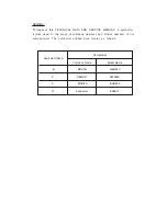
Page 2: ...WALT DW004K P BOSCH GBH24V B MAKITA BHR200 C Panasonic EZ6813 Q REMARK Throughout this TECHNICAL DATA AND SERVICE MANUAL a symbol s is are used in the place of company name s and model name s of our competitor s The symbol s utilized here is are as follows ...

Page 3: ...15 7 1 Handling Instructions 15 7 2 Caution Plates 17 7 3 Precautions Requiring Particular Attention During Sales Promotion 18 8 REFERENCE MATERIAL 19 8 1 Lubrication 19 8 2 Tool Structure 19 8 3 Rotation Only and Rotation Striking Changeover Mechanism 22 8 4 Rotation Only No striking 22 8 5 Drill Bits 22 8 6 Tool Retainer Section 23 8 7 Dust Collector B 24 9 PRECAUTIONS IN DISASSEMBLY AND REASSEM...

Page 4: ...d removed easily as they are slide type batteries The main components of the hammering mechanism and the tool retainer are common with the Model DH 24PB2 3 APPLICATIONS 1 Rotation and striking function Drilling anchor holes Drilling holes in concrete tile brick and similar materials 2 Rotation only function Drilling holes in steel and wood with chuck adapter Tightening and loosening machine screws...

Page 5: ... the bit from being bent Cylindrical gear cover Increased in sturdiness and reliability Powerful and advanced design B and C Constructed of two parts Replaceable carbon brushes The carbon brushes can be replaced by loosening the two screws and removing the grip cover B P and Q Not replaceable One push tool retainer eliminates the need for sliding the grip at mounting the bit Sliding the grip is re...

Page 6: ...e For drilling holes in 5 mm or more diameter speedily SAVE Suppressing mode For drilling holes in 4 8 mm or less diameter preventing the bit from being bent The Model DH 24DV can also be used for drilling holes into soft workpieces by decreasing the hammering force Following figures show a comparison of the brick breakage when drilling holes into bricks as a guide of the hammering force Drilling ...

Page 7: ...l direction The double layer molded grip cover consists of a resin base covered with a soft resin to ensure a soft touch and non slip grip of the handle Drilling in horizontal direction Drilling in upward direction It is easy to hold because this portion reduces the massive feeling It is well balanced by holding the rear of the motor B ...

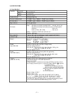
Page 8: ...FB 0 6 kg 1 3 lbs Type of motor DC magnet motor No load rotation speed POWER mode 1 000 min SAVE mode 500 min Type of switch Trigger switch with forward reverse rotation selector with brake D type handle with side handle Handle shape 5 SPECIFICATIONS 5 1 Specifications Capacity Usable drill bits 24 mm 15 16 SDS plus type only 13 mm 1 2 30 mm 1 3 16 Concrete Steel Wood Full load blow Enclosure Body...

Page 9: ...or charger is faulty During charging Prior to charging Charging completed High battery temperature Standard accessories Charging not possible Charging not possible because storage battery temperature is too high Blinks Blinks Lit Lit Flickers 0 5 sec ON 0 5 sec OFF 0 5 sec ON 0 5 sec OFF Stays ON constantly 0 1 sec ON 0 1 sec OFF Stays ON constantly Pilot lamp indications UC 24YFB ...

Page 10: ... No 306369 306368 306370 Code No Adapter for slender shaft Drill bit slender shaft 1 Drill bit taper shank 2 Taper shank adapter SDS plus shank Drill bit taper shank 21 5 27 32 944464 Morse taper No 2 303618 3 Cotter Straight shank bit for impact drills 13 mm 1 2 hammer drill chuck SDS plus shank 13 mm hammer drill chuck For drilling operations when using a straight shank bit for impact drilling w...

Page 11: ... Overall length 260 260 160 260 Internal cone type External cone type Anchor setting bar for manual anchor setting Anchor setting adapter Part name W 1 4 Anchor setting adapter A W 5 16 Anchor setting adapter A W 3 8 Anchor setting adapter A W 1 2 Anchor setting adapter A W 5 8 Anchor setting adapter A Code No 971794 971795 971796 971797 971798 Part name W 1 4 Anchor setting adapter B W 5 16 Ancho...

Page 12: ...huck adapter G Chuck wrench 0 8 1 1 Cross recessed head Phillips bit Overall length 65 mm For use with cross recessed head Phillips screw 2 Slotted head minus bit Overall length 50 mm For use with slotted head minus screw Stamped bit No Tip thickness Applicable screw dia mm 3 5 6 8 Bit No No 2 No 3 Code No 955654 955655 Applicable screw dia mm 4 5 6 Bit tip thickness Code No 955658 955673 321825 3...

Page 13: ...y attaching it directly to chuck adapter D Chuck adapter D SDS plus shank Chuck wrench Bit No Chuck adapter D SDS plus shank Phillips plus driver bit overall length 25 mm for cross recessed head screw Chuck adapter D for SDS plus shank type 13 mm 1 2 Drill chuck 13VLD D with chuck wrench Part name Code No 303624 321813 3 5 mm 6 8 mm Bit No No 2 No 3 Code No 971511Z 971512Z Screw size G Grease for ...

Page 14: ... 11 Code No 971787 Code No 306885 H Dust cup dust collector B Dust cup Dust collector B ass y ...

Page 15: ...ting Hammering only function Soft grip handle Safety slip clutch 50 70 Externally accessible CB Variable speed Brake Charging time Ah Dimension Length Height kg min 24 2 0 3 0 Nicd NiMH 292 211 3 7 50 70 24 2 0 3 0 329 235 3 8 18 60 24 2 0 348 215 4 2 60 24 2 0 316 235 4 0 40 24 3 0 316 206 4 35 45 24 3 0 Double action Single action Single action Single action Single action Nicd NiMH Nicd Nicd NiM...

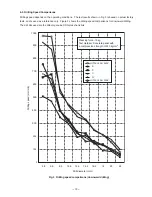
Page 16: ...I DH 20DV Drill diameter mm Drilling speed mm min 6 2 Drilling Speed Comparisons Drilling speed depends on the operating conditions The test results shown in Fig 3 is based on actual factory tests and is used as a reference only Figure 3 shows the drilling speed comparisons for downward drilling The drill bits used are the Hitachi genuine SDS plus shank bits Fig 3 Drilling speed comparisons downwa...

Page 17: ...40 160 180 200 220 240 260 280 300 295 214 264 267 137 120 220 156 178 205 137 128 140 104 114 98 98 70 81 86 55 69 80 58 48 31 48 62 38 36 32 41 45 28 29 60 48 26 41 30 18 45 17 27 25 18 17 30 15 B C P Q B C P Q B C P Q B C P Q B C P Q B C P Q B C P Q B C P Q B C P Q DH 24DV DH 20DV B C P Q Model Battery capacity mAh 3 000 2 000 2 000 3 000 3 000 2 000 93 129 72 74 93 33 6 3 Per Charge Working Ca...

Page 18: ...wer outlet only Use of any other power source DC outlet fuel powered generator etc will cause the charger to overheat and burnout 4 Do not use any voltage increasing equipment transformer etc between the power source and the charger If the charger is used with voltage over and above that indicated on the unit it will not function properly 5 Conduct battery charging at an ambient temperature range ...

Page 19: ...d charger to permit rapid charging Incorrect parts replacement and or wiring will cause malfunctions which could result in fire or other hazard Instruct the customer to bring these units to an authorized service center in the event repair or replacement is necessary 10 Disposal of the Models EB 2420 and EB 2430H batteries Ensure that all customers understand that the Models EB 2420 and EB 2430H ba...

Page 20: ...e Plate attached to each of the Models EB 2420 and EB 2430HA batteries CAUTION Read thoroughly HANDLING INSTRUCTIONS before use Do not disassemble nor throw into fire For Europe CAUTION For safe operation see instruction manual Use HITACHI charger recommended in instruction manual for recharging For the U S A anc Canada 3 The following cautions are listed on the Name Plate attached to each Model U...

Page 21: ...ve pressure will reduce bit rotation and hammering speed and cause the storage battery to rapidly lose its charge 3 Variation in amount of work possible per charge Although the nominal capacity of the storage batteries used with the Model DH 24DV is 2 000 mAh the actual capacity may vary within the range of 1 800 to 2 200 mAh depending on the ambient temperature during use and recharging and the n...

Page 22: ...er The cylinder is coupled to the second gear by means of a slip mechanism and they rotate together The end of the cylinder also functions as the drill bit retainer The cylinder is key connected to the inserted drill bit by means of two key rails and transmits rotation to the drill bit A steel ball is used to prevent the bit from coming off Piston reciprocating mechanism In conventional hammer dri...

Page 23: ...ended that the O ring be replaced approximately once a year depending on the frequency of usage of the tool Idle striking prevention mechanism The idle striking prevention mechanism in the Model DH 24DV is different from that of conventional hammer drills When the drill bit is lifted from the concrete surface on completion of drilling the second hammer moves to the position indicated by the contin...

Page 24: ...ntact with a reinforcing bar within the concrete causing sudden excessive torque the slip mechanism functions to prevent damage to the gears and possible loss of control of the tool by the operator Sealed and dustproof construction The gear cover is totally enclosed by oil seals O rings and other devices to prevent leakage of lubricating grease and to keep dust and dirt out of the internal mechani...

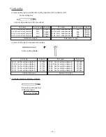
Page 25: ...ond shaft When the change lever is returned to the rotation striking mark position the force of the clutch spring presses the clutch back against the reciprocating bearing so that the claws engage to transmit rotation to the reciprocating bearing once more 8 4 Rotation Only No striking The Model DH 24DV is equipped with a change lever for changeover between rotation striking and rotation only func...

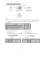
Page 26: ... Section Figure 9 shows the construction of the chuck section The tool retainer is structured as shown in Fig 9 The tip of the tool retainer is covered with the front cap made of rubber to prevent dust and chips from getting inside The steel ball falls into the round groove of the bit to prevent the tool from coming off and the two key rails transmit the rotation torque To mount the bit push the b...

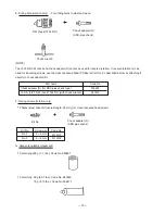
Page 27: ...erves as a ball bearing Should the dust cover be forced against the concrete surface it will not rotate even though the tool shank continues to rotate Should the tool be operated when the dust cover is not being held against a concrete surface inertia may cause dust collector B to become disconnected from the grip Accordingly caution the customer to press dust collector B and drill bit firmly agai...

Page 28: ...o the Carbon Brushes 61 Remove from the end of the Second Shaft 41 and turn the Second Shaft 41 so that the Piston 36 moves to its maximum upper position inner cover side The arm of the Reciprocating Bearing 46 can then be disconnected from the Piston Pin 45 and the Second Shaft 41 and the components mounted on it can be removed from the Inner Cover Ass y 39 as a unit With a bearing puller remove ...

Page 29: ...1 from the Gear Cover 10 with a hand press Then Sleeve A 14 can be removed from the Cylinder 21 Remove the Retaining Ring for D30 Shaft 25 from the Cylinder 21 with a retaining ring puller Then the Second Gear 22 Spring A 23 and Washer A 24 can be removed from the Cylinder 21 4 Disassembly of the cylinder and the second hammer Remove the Stopper Ring 33 from the inside diameter portion of the Cyli...

Page 30: ...e and Pinion Ass y DC 24 V 55 At this time be careful not to damage the carbon brushes The Inner Cover Ass y 39 and the Armature and Pinion Ass y DC 24 V 55 can be removed just by pressing the Pinion 50 slightly with a press because there is an interference of the O ring 53 The housing is constructed of two parts Remove the Tapping Screw W Flange D4 x 20 Black 65 to disassemble the housing 6 Disas...

Page 31: ...ion of the Change Lever 19 Apply HITACHI Motor Grease No 29 to the O ring S 18 18 for the Steel Ball D7 0 20 and the Change Lever 19 Application of Hitachi Motor Grease No 29 makes it easy to mount the Spacer 49 2 Mounting the Change Lever 19 Position the Change Lever 19 on the Gear Cover 10 as shown in Fig 16 and push it in firmly Adjust the Change Lever 19 to the position where mark points in th...

Page 32: ...34 Inner Cover Ass y 39 First Gear 48 6 Perform wiring as shown in Fig 18 Fig 18 Wiring arrangement and port locations Viewed from A Section B B Internal wire Brown Internal wire Black Internal wire Red Internal wire Blue Internal wire Red Internal wire Black Upper side brown Lower side blue A B ...

Page 33: ... 30 9 3 Precautions on Disassembly and Reassembly of the Charger Please refer to Technical Data and Service Manual for Model UC 24YFB for precautions on disassembly and resassembly ...

Page 34: ...all Bearing 608DD Brush Holder Terminal Support DC Speed Control Switch Inner Cover Ball Bearing 626VV Second Shaft Clutch Spring Clutch Reciprocating Bearing First Gear Pinion Ball Bearing 626VV General Assembly Housing A B Set Second Hammer O ring 1AP 20 Hammer Holder O ring B Damper A O ring C Damper Holder Cylinder Second Gear Spring A Front Cap Grip Ball Holder Holder Spring Steel Ball D7 0 G...

Page 35: ...2004 6 10 E1 Hitachi Power Tools 1 2 3 4 5 6 7 8 10 501 502 16 17 18 19 9 11 12 13 14 15 20 21 22 23 24 25 50 38 39 53 54 55 56 57 58 65 66 67 59 61 52 63 64 70 60 62 68 69 71 72 75 76 77 78 73 74 51 52 26 27 28 29 30 31 32 33 34 35 36 45 37 40 41 42 43 44 46 47 48 49 503 504 ...

Page 36: ...TEEL BALL D7 0 10 PCS 1 21 322 814 CYLINDER 1 22 301 677 SECOND GEAR 1 23 316 135 SPRING A 1 24 301 679 WASHER A 1 25 948 310 RETAINING RING FOR D30 SHAFT 1 26 322 803 SECOND HAMMER 1 27 944 486 O RING 1AP 20 1 28 322 804 HAMMER HOLDER 1 29 322 802 O RING B 1 30 322 805 DAMPER A 1 31 322 808 O RING C 1 32 322 806 DAMPER HOLDER 1 33 322 807 STOPPER RING 1 34 322 801 STRIKER 1 35 322 834 O RING I D ...

Page 37: ...IR 2 62 323 166 INTERNAL WIRE RED 1 63 323 165 INTERNAL WIRE BLACK 1 64 323 158 PUSHING BUTTON 1 65 302 086 TAPPING SCREW W FLANGE D4X20 BLACK 6 66 NAME PLATE 1 67 323 171 HOUSING A B SET GREEN 1 68 323 163 TERMINAL SUPPORT 1 69 318 247 FERRITE CORE 1 70 319 811 DC SPEED CONTROL SWITCH 1 71 319 812 HEAT SINK 1 72 993 963 MACHINE SCREW W WASHERS M3X12 1 73 HITACHI LABEL 1 74 323 159 SHIFT KNOB 1 75...

Page 38: ...ODE NO DESCRIPTION REMARKS NO USED 6 04 DH 24DV STANDARD ACCESSORIES Printed in Japan 040610N 501 323 155 SIDE HANDLE 1 502 303 709 DEPTH GAUGE 1 502 310 331 DEPTH GAUGE 1 FOR USA CAN 503 CHARGER MODEL UC 24YFB 1 504 323 350 CASE 1 ...

Page 39: ......

Reviews: