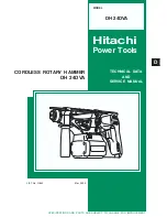
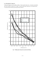
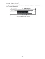
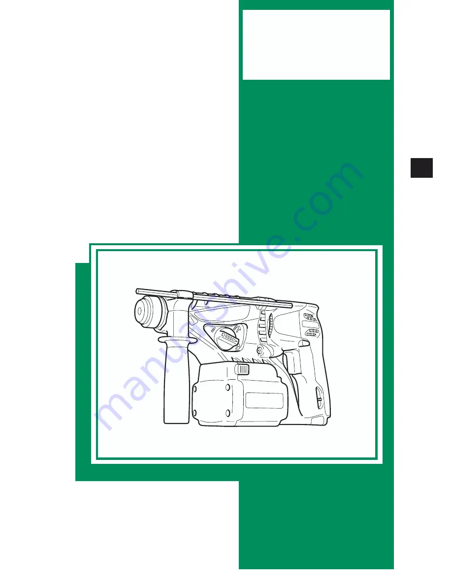
Hitachi DH 24DVA, Technical Data And Service Manual
The Hitachi DH 24DVA is a powerful and versatile manual drill designed for precise and efficient drilling tasks. Get your hands on the comprehensive Handling Instructions Manual for this outstanding tool, available for free download on our website. Discover all the essential details and operating guidelines to maximize your drilling experience.
Share
Download


Reviews:
No comments
Related manuals for DH 24DVA

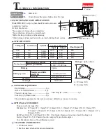
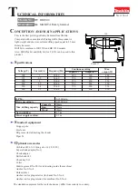
BHR202
Brand: Makita Pages: 3
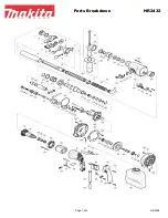
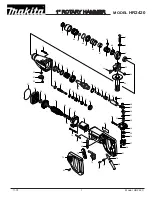
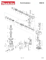
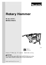
HR2432
Brand: Makita Pages: 4
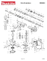
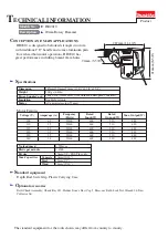
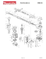
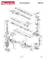
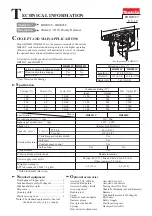
HR3000C
Brand: Makita Pages: 4
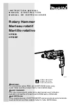
HR2010
Brand: Makita Pages: 6
HR2420
Brand: Makita Pages: 5
HR4041C
Brand: Makita Pages: 3
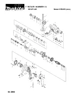
HR4040C
Brand: Makita Pages: 14
HR4030C
Brand: Makita Pages: 13
HR2450F
Brand: Makita Pages: 18
HR2300
Brand: Makita Pages: 23
HR4510C
Brand: Makita Pages: 4
HR4013C
Brand: Makita Pages: 19
HR2010
Brand: Makita Pages: 3
HR2450 Series
Brand: Makita Pages: 5
HR2000
Brand: Makita Pages: 6
HR2010
Brand: Makita Pages: 16
HR1830F
Brand: Makita Pages: 28
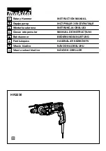
HR2230
Brand: Makita Pages: 40


