--- 25 ---
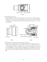
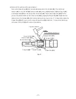
(2) Disassembly of the dust collection adapter ass'y
Disassembly of the Hose Ass'y
[98]
only
Loosen the knob that fixes the stopper, and push pipe (A) to its maximum stroke position. This will cause the
Hose Ass'y
[98]
connection portion of pipe (A) to come out of the rear end of pipe (B). In that state, pull on the
Hose Ass'y
[98]
to separate it from pipe (A).
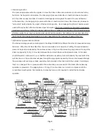
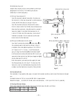
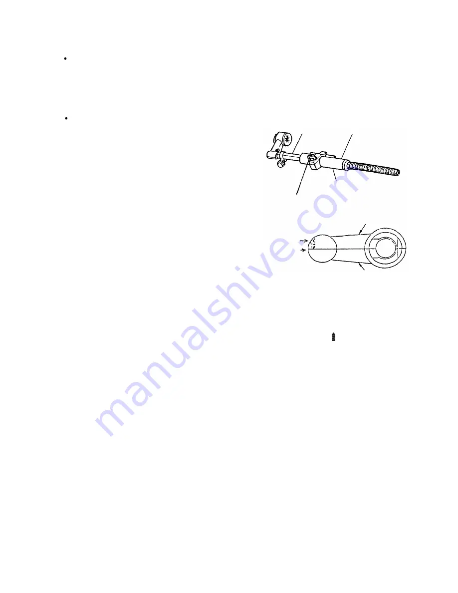
Disassembly of the dust collection adapter ass'y (Refer to Fig. 13.)
Disassemble the Rubber Cap
[94]
and the Nozzle Seal
[93]
from the nozzle portion, and remove the screw that
fastens nozzle (A) and nozzle (B). While pressing the
claw head of nozzle (B) in the direction indicated by
arrow "A" in Fig. 13, insert the tip of a thin flat-blade
screwdriver between the surfaces in front of the claw-
connected portion and pry up gently to disengage the
claw so that nozzle (A) and nozzle (B) can be removed
from pipe (A). Next, take the stopper off from pipe (A),
and remove the O-ring from the tail cap side so that the
tail cap can be removed from pipe (B). Pipe (A) can then
be taken out from pipe (B) by enlarging its split section
after removing the retaining wing bolt.
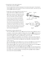
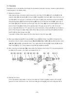
(3) Disassembly of the striking mechanism section
Remove the Striker
[35]
chucked with O-ring (C)
[32]
by pushing in the Second Hammer
[27]
with a drill bit or
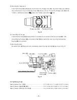
a screwdriver. Turn the Change Lever
[14]
135
û
clockwise from the "rotation only" ( mark) position pressing
the Pushing Button
[12]
deeply. Pry the Change Lever
[14]
off in this position. Remove the Tapping Screw
(W/Flange) D5 x 90
[9]
from the Gear Cover
[10]
and remove the Gear Cover
[10]
.
The Inner Cover
[39]
and the Housing
[72]
are loosely fitted together. Attempting to pull them out first could
cause the Armature
[67]
to be pulled out at the same time, causing damage to the Carbon Brushes
[76]
. For
directions on how to remove the Gear Cover
[10]
, please refer to paragraph (1) "Disassembly of the dust
collection mechanism".
Remove the Spacer
[42]
and Spring (B)
[43]
from the end of the Second Shaft
[44]
and turn the Second Shaft
[44]
so that the Piston
[37]
moves to its maximum upper position (inner cover side). The arm of the
Reciprocating Bearing
[48]
can then be disconnected from the Piston Pin
[40]
, and the Second Shaft
[44]
and
the components mounted on it can be removed from the Inner Cover
[39]
as a unit.
With a bearing puller, remove the First Gear
[49]
from the Second Shaft
[44]
. Then take off the Reciprocating
Bearing
[48]
. At this time, carefully note that the First Gear
[49]
must be aligned with and press-fitted onto the
9-mm diameter end of the Second Shaft
[44]
. The Clutch
[47]
, Clutch Spring
[46]
and Washer (B)
[45]
can
then be removed from the Second Shaft
[44]
.
Hose Ass'y
[98]
Fig. 13
Retaining wing bolt
Pipe (A)
Nozzle (B)
Connection
surfaces
Nozzle (A)
Pipe (B)
A
Summary of Contents for DH 24PD2
Page 26: ... 23 Fig 10 Dust collector B structure ...
Page 44: ......


