--- 26 ---
9-2. Reassembly
Reassembly can be accomplished by following the disassembly procedure in reverse. However, special attention
should be given to the following items.
(1) Application of lubricant
Apply special grease (for hammer and hammer drill) to the O-ring (1AP-20)
[29]
and O-ring (B)
[31]
for the
Damper Holder
[30]
, Damper (A)
[32]
, O-ring (C)
[33]
, O-ring (I.D. 16)
[37]
for the Striker
[36]
, outer
circumference of the Striker
[36]
, inner and outer circumference of the Piston Pin
[49]
, outer circumference of
the Piston
[38]
, Reciprocating Bearing
[61]
, Reciprocating Bearing
[61]
rotary shaft of the Second Shaft
[57]
,
clutch claw of the Cylinder
[18]
, inner circumference of the metal of the Inner Cover Ass'y
[40]
, Second
Hammer
[28]
, and the lip portion of the Oil Seal
[12]
. Fill 45 g of the special grease in the gear cover and 5 g
in the inner cover groove. Apply Molub Alloy No. 777-1 grease to the outer circumference of the Clutch
[60]
groove and the pin portion of the Change Lever
[25]
. Apply Hitachi Motor Grease No. 29 to the O-ring (S-18)
[24]
for the Steel Ball D7.0
[17]
and the Change Lever
[25]
.
* Application of Hitachi Motor Grease No. 29 makes it easy to mount the Spacer
[55]
.
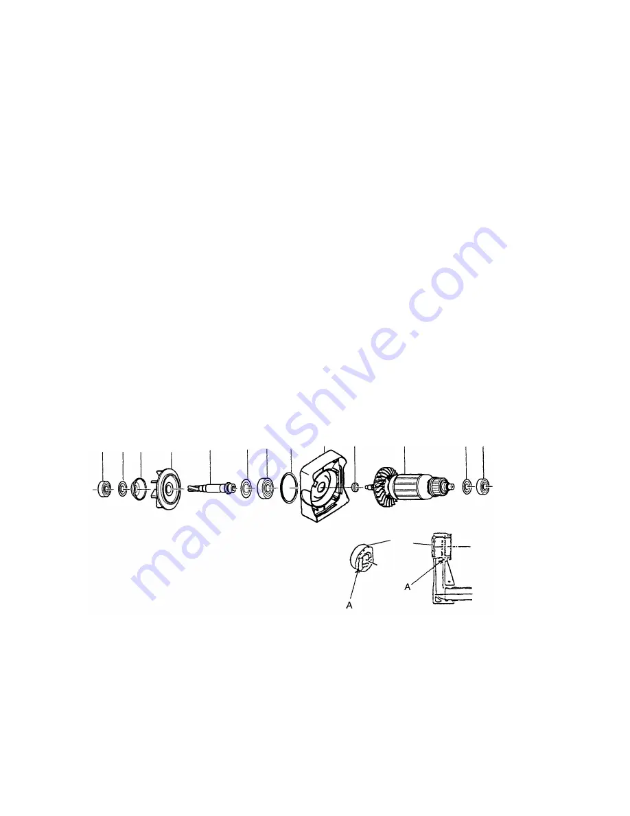
(2) When assembling Housing
[77]
, Casing (A)
[69]
, Casing (B)
[46]
and Gear Cover
[10]
, at first perform
assembling of the dust collection mechanism ass'y
[44]
,
[45]
,
[47]
,
[48]
and
[65]
to
[69]
and the armature
section (
[70]
,
[71]
,
[45]
and
[75]
) as illustrated below. Then, reassemble the Housing
[77]
, Casing (B)
[46]
and the Gear Cover
[10]
(Fig. 19). This procedure will significantly facilitate reassembly.
(3) When mounting the Nozzle Seal
[96]
, ensure without fail that the section marked "A" is properly aligned with
and fitted into the groove on the nozzle, as indicated in Fig. 20.
[44]
Fig. 19
[67]
[66]
[45][47]
[48]
[65]
[68]
[95]
[75]
[69]
[70]
[71]
[45]
Fig. 20
Summary of Contents for DH 24PD3
Page 44: ......


