background image

7

28. BLADES AND ACCESSORIES MUST BE SECURELY MOUNTED TO THE TOOL.

Prevent potential injuries to yourself or others. Blades, cutting implements and
accessories which have been mounted to the tool should be secure and tight.

29. KEEP MOTOR AIR VENT CLEAN.

The tool’s motor air vent must be kept clean so that air can freely flow at all
times. Check for dust build-up frequently.

30. OPERATE POWER TOOLS AT THE RATED VOLTAGE.

Operate the power tool at voltages specified on their nameplates.
If using the power tool at a higher voltage than the rated voltage, it will result in
abnormally fast motor revolution and may damage the unit and burn up the
motor.

31. NEVER USE A TOOL WHICH IS DEFECTIVE OR OPERATING ABNORMALLY

If the tool appears to be operating unusually, making strange noises, or other-
wise appears defective, stop using it immediately and arrange for repairs by a
Hitachi authorized service center.

32. NEVER LEAVE TOOL RUNNING UNATTENDED. TURN POWER OFF.

Don’t leave tool until it comes to a complete stop.

33. CAREFULLY HANDLE POWER TOOLS.

Should a power tool be dropped or struck against hard materials inadvertently
it may be deformed, cracked, or damaged.

34. DO NOT WIPE PLASTIC PARTS WITH SOLVENT.

Solvents such as gasoline, thinner, benzine, carbon tetrachloride, and alcohol
may damage and crack plastic parts. Do not wipe them with such solvents.
Wipe plastic parts with a soft cloth lightly dampened with soapy water and dry
thoroughly.

35. USE ONLY AUTHENTIC HITACHI REPLACEMENT PARTS.

Replacement parts not manufactured by Hitachi may void your warranty and
can lead to malfunction and resulting  injuries. Authentic Hitachi parts are avail-
able from your dealer.

Summary of Contents for DH 24VB

Page 1: ... manual contains important information about prod uct safety Please read and understand this manual before operating the power tool Please keep this manual avail able for others before they use the power tool DOUBLE INSULATION INSTRUCTION MANUAL AND SAFETY INSTRUCTIONS FOR ROTARY HAMMER MODEL DH 24VB ...

Page 2: ...ACEMENT PARTS 8 POLARIZED PLUGS 8 USE OF EXTENSION CORD 9 DOUBLE INSULATION FOR SAFER OPERATION 10 OPERATION AND MAINTENANCE NAME OF PARTS 11 SPECIFICATIONS 11 ACCESSORIES 12 STANDARD ACCESSORIES 12 OPTIONAL ACCESSORIES 12 APPLICATIONS 17 PRIOR TO OPERATION 17 HOW TO USE 19 HOW TO USE THE CORE BIT FOR LIGHT LOAD 23 LUBRICATION 24 MAINTENANCE AND INSPECTION 25 SERVICE AND REPAIRS 25 PARTS LIST 26 ...

Page 3: ...on of this Instruction Manual and in the sections which contain the operation and maintenance instruc tions Hazards that must be avoided to prevent bodily injury or machine damage are iden tified by WARNINGS on the power tool and in this Instruction Manual Never use this power tool in a manner that has not been specifically recommended by HITACHI unless you first confirm that the planned use will ...

Page 4: ...ent eye protection Wear ear protection to protect yourself from excessive noise 4 PROTECT YOURSELF AGAINST ELECTRIC SHOCK Prevent body contact with grounded surfaces such as pipes radiators ranges and refrigeration enclosures Never operate the tool in damp or wet locations 5 DISCONNECT TOOLS Never leave the tool connected to a power source Always disconnect the tool from its power source before se...

Page 5: ...e limbs or logs 13 DRESS PROPERLY Do not wear loose clothing or jewelry They can be caught in moving parts Rubber gloves and non skid footwear are recommended when working out doors Wear protective hair covering to contain long hair 14 USE FACE DUST MASK OR RESPIRATOR IF OPERATION IS DUSTY All persons in the area where power tools are being operated should also wear face dust masks or respirator 1...

Page 6: ...ss otherwise indicated elsewhere in this Instruction Manual Have defective switches replaced by authorized service center Do not use tool if switch does not turn it on and off 23 NEVER USE A POWER TOOL FOR APPLICATIONS OTHER THAN THOSE SPECI FIED Never use a power tool for applications other than those specified in the In struction Manual 24 HANDLE TOOL CORRECTLY Operate the tool according to the ...

Page 7: ...s to be operating unusually making strange noises or other wise appears defective stop using it immediately and arrange for repairs by a Hitachi authorized service center 32 NEVER LEAVE TOOL RUNNING UNATTENDED TURN POWER OFF Don t leave tool until it comes to a complete stop 33 CAREFULLY HANDLE POWER TOOLS Should a power tool be dropped or struck against hard materials inadvertently it may be defo...

Page 8: ... underground wiring Touching these active wiring or electric cable with this tool you may receive an electric shock Comfirm if there are any buried object such as electric cable within the wall floor or ceiling where you are going to operate here after REPLACEMENT PARTS When servicing use only identical replacement parts Repairs should be conducted only by a Hitachi authorized service center POLAR...

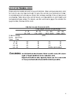
Page 9: ...f in doubt use the next heavier gage The smaller the gage number the heavier the cord MINIMUM GAGE FOR CORD SETS Total Length of Cord in Feet Meter 0 25 26 50 51 100 101 150 0 7 6 7 9 15 2 15 5 30 5 30 8 45 7 Ampere Rating AWG More Not More Than Than 0 6 18 16 16 14 6 10 18 16 14 12 10 12 16 16 14 12 12 16 14 12 Not Recommended WARNING Avoid electrical shock hazard Never use this tool with a dam a...

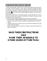
Page 10: ...s no external grounding you must still follow the normal electrical safety precautions given in this Instruction Manual including not using the power tool in wet environments To keep the double insulation system effective follow these precautions s Only HITACHI AUTHORIZED SERVICE CENTER should disassemble or assemble this power tool and only genuine HITACHI replacement parts should be in stalled s...

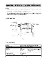
Page 11: ... details or attachments that differ from those on your own power tool NAME OF PARTS Fig 1 SPECIFICATIONS Motor Single Phase Series Commutator Motor Power Source Single Phase 115V AC 60Hz Current 4 6A Capacity Concrete 1 8 15 16 3 4mm 24mm Steel 1 2 13mm Wood 1 1 4 32mm No Load Speed 0 1000 min Full load Impact Rate 4200 min Weight 5 1 lbs 2 3 kg Grip Nameplate Front Cap Drill Bit Depth Gauge Side ...

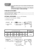
Page 12: ...ank adaptor 1 Drill Bit Taper Shank 2 Taper Shank Adaptor SDS plus Shank Cotter Code No 944477 ACCESSORIES WARNING Accessories for this power tool are mentioned in this Instruction Manual The use of any other attachment or accessory can be dangerous and could cause injury or mechanical damage STANDARD ACCESSORIES 1 Case Modeled plastic Code No 307786 1 2 Side Handle Code No 303659 1 3 Depth Gauge ...

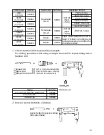
Page 13: ...3 mm Hammer Drill chuck and Chuck wrench For drilling operations when using a straight shank bit for impact driling with a hammer drill 1 2 13 mm Hammer Drill Chuck SDS plus Shank include Chuck wrench Chuck wrench Name Code No 1 2 13 mm Hammer Drill Chuck 303332 Chuck wrench 303334 Rubber Cap 303335 2 Knock in anchor Rotation Striking Anchor Setter for anchor setting SDS plus Shank Impact Drill Ap...

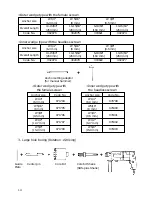
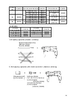
Page 14: ... 19 64 10 15 64 260 mm 260 mm 160 mm 260 mm Code No 302979 302978 303622 302977 Anchor setting adaptor for manual hammer Outer wedge type with the female screw Anchor size Code No W1 4 971794 6 3 mm W5 16 971795 8 mm W3 8 971796 9 5 mm W1 2 971797 12 7 mm W5 8 971798 15 9 mm Inner wedge type with the headless screw Anchor size Code No W1 4 971799 6 3 mm W5 16 971800 8 mm W3 8 971801 9 5 mm W1 2 97...

Page 15: ...de N0 Code No Code No Guide plate Core bit outer diameter 1 1 4 32 mm 1 3 8 35 mm 1 1 2 38 mm Core bit outer diameter 1 25 32 45 mm 1 31 32 50 mm Code No 982686 982687 982688 Code No 982689 982690 4 Breaking operation rotation striking Bull point Round type only SDS plus Shank Code No 303046 5 Bolt placing operation with Chemical Anchor rotation striking Standard socket on the market SDS plus Shan...

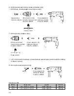
Page 16: ...ling holes rotation only Drill chuck 13VLA include chuck wrench Code No 950272 Chuck adaptor D SDS plus Shank Code No 303624 Chuck wrench s 1 2 13 mm drill chuck ass y include chuck wrench ass y and chuck for drilling in steel or wood 8 Driving Screws rotation only Bit No Chuck adaptor D SDS plus Shank Code No 303624 Plus Driver Bit Bit No Screw Size Length Code No No 2 1 8 3 16 3 5 mm 31 32 25 mm...

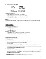
Page 17: ...ith optional accessories s Tightening machine screws wood screws PRIOR TO OPERATION 1 Power source Ensure that the power source to be utilized conforms to the power source re quirements specified on the product nameplate 2 Power switch Ensure that the switch is in the OFF position If the plug is connected to a recep tacle while the switch is in the ON position the power tool will start operating i...

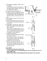
Page 18: ...ary hammer for up ward drilling operations attach a dust cup or a dust collector B to collect dust or particles for easy operation s Installing the dust cup Use the dust cup by attaching to the drill bit a shown in Fig 3 When using a bit which has big diam eter enlarge the center hole of the dust cup with this rotary hammer s Installing the dust collector B When using the dust collector B in sert ...

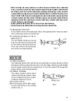
Page 19: ... heads or bits will be damaged unless a bit appropriate for the screw diam eter is employed to drive in the screws 8 Confirm the direction of bit ro tation Fig 5 The bit rotates clockwise viewed from the rear side by pushing the R side of the reversing switch lever The L side of the lever is pushed to turn the bit counterclockwise HOW TO USE 1 Switch operation The rotational speed of the drill bit...

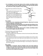
Page 20: ...ws Installing drill chuck and chuck adaptor Fig 9 1 Attach the drill chuck to the chuck adap tor 2 The part of the SDS plus shank is the same as the drill bit Therefore refer to the item of Mounting the drill bit for attaching it CAUTION s Application fo force more than neces sary will not only expedite work at all but will deteriorate the tip edge of the drill bit and reduce the service life of t...

Page 21: ...crew s Do not attempt to use the rotary hammer in the rotation and striking function with the chuck adaptor D and bit attached 5 When driving wood screws Fig 10 1 Selecting a suitable driver bit Employ plus head screws if possible since the driver bit easily slips off the heads of minus head screws 2 Driving in wood screws s Prior to driving in wood screws make pilot holes suitable for them in the...

Page 22: ... Mount the taper shank adaptor to the rotary hammer Fig 12 2 Mount the drill bit taper shank to the taper shank adaptor Fig 12 3 Turn the switch ON and drill a hole in prescribed depth 4 To remove the drill bit taper shank insert the cotter into the slot of the taper shank adaptor and strike the head of the cotter with a hammer supporting on the rest Fig 13 Depth Gauge Mounting Hole Knob on Side H...

Page 23: ...d in the center pin Push it lightly to the wall or the floor straight Connect all over the surface of the core bit tip and start operating 3 When boring about 3 16 5 mm in depth the position of the hole will es tablish Bore after that removing the center pin and the guide plate from core bit 4 Application of excessive force will not only expedite the work but will dete riorate the tip edge of the ...

Page 24: ...n be removed LUBRICATION Low viscosity grease is applied to this rotary hammer so that it can be used for a long period without replacing the grease Please contact the nearest service agent for grease replacement when any grease is leaking from loosened screw Further use of the rotary hammer despite the grease shortage causes seizure to reduce the service life CAUTION A specific grease is used wit...

Page 25: ...emely dan gerous 3 Inspecting the carbon brushes For your continued safety and electrical protection carbon brush inspection and replacement on this tool should ONLY be performed by a HITACHI AUTHORIZED SERVICE CENTER 4 Maintenance of the motor The motor unit winding is the very heart of the power tool Exercise due care to ensure the winding does not become damaged and or wet oil or water SERVICE ...

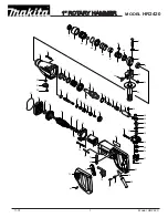
Page 26: ...26 ...
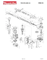
Page 27: ...her B 36 Clutch Spring 37 Clutch 38 O Ring S 8 Item Part Name No 39 Reciprocating Bearing 40 First Gear 41 Feather Key 3x3x8 42 Spacer 43 Ball Bearing 626VVMC2ERPS2S 44 O Ring P 22 45 Ball Bearing 608DDMC2EPS2S 46 Washer A 47 Armature 48 Fan Guide Ass y 49 Rubber Bushing 50 Stator C 51 Ball Bearing 608VVMC2EPS2L 52 Housing 53 Name Plate 54 Tapping Screw W Flange D4x20 55 Handle Cover 56A Speed Con...

Page 28: ...Nippon Bldg 6 2 Ohtemachi 2 chome Chiyoda ku Tokyo 100 Japan 603 Code No C99055362 N Printed in Japan ...

Reviews: