-17-
Be sure to disconnect the power cord plug from the wall outlet before conducting repair. Otherwise, the
motor may suddenly run, posing a very dangerous situation.
1. Precautions on Disassembly and Reassembly
The
[Bold]
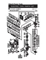
numbers in the descriptions below correspond to item numbers in the parts list and exploded
view assembly diagram for the Model DH 28PC.
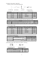
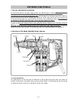
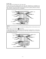
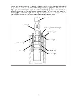
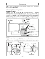
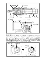
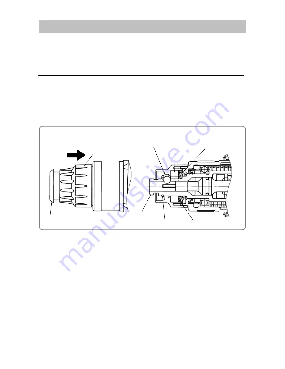
1. Disassembly of the tool retainer
Fully pull Grip
[3]
in the arrow direction and remove Front Cap
[1]
. Forcefully pull Front Cap
[1]
to remove it
from Cylinder
[21]
.
Then remove Stopper Ring
[29]
by using the stopper ring puller while pulling Grip
[3]
. You can then remove
Grip
[3]
, Ball Holder
[4]
, Steel Ball D7.0
[20]
, Holder Plate
[5]
, and Holder Spring
[6]
from Cylinder
[21]
.
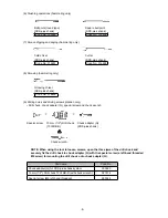
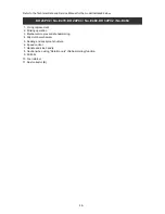
2. Disassembly of the hammering mechanism
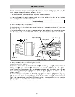
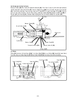
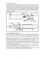
(a) Cylinder Case and Cylinder
First, remove Seal Lock Hex. Socket Hd. Bolt M4 x 12
[57]
from Change Lever
[58]
, and then demount
Change Lever
[58]
and Lever Holder
[59]
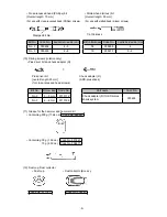
. Remove Hex. Socket Hd. Bolt (W/Flange) M4 x 10
[43]
, Hex.
Socket Hd. Bolt (W/Flange) M5 x 16
[98]
, Tapping Screw (W/Flange) D5 X 20 (Black)
[78]
, and Tapping
Screw (W/Flange) D4 X 25 (Black)
[44]
. Remove Handle (A). (B) Set
[40]
from Crank Case
[104]
and
Housing Ass'y
[74]
.
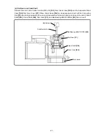
Then remove Tapping Screw (W/Flange) D4 X 16 (Black)
[82]
. Remove Tail Cover
[81]
from Housing Ass'y
[74]
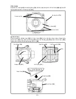
. Remove Hex. Socket Hd. Bolt (W/Flange) M5 x 16
[98]
from Crank Cover
[99]
, and then demount
Crank Cover
[99]
and Rubber Seal
[102]
from Crank Case
[104]
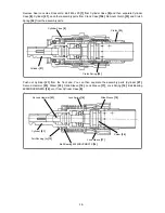
. Remove Retaining Ring For D35 Hole
[60]
by using stopper ring puller and demount Lever Shaft
[61]
.
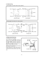
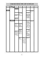
REPAIR GUIDE
Front Cap
[1]
Grip
[3]
Cylinder
[21]
Stopper Ring
[29]
Holder Spring
[6]
Holder Plate
[5]
Steel Ball D7.0
[20]
Ball Holder
[4]
Disassembly

