-23-
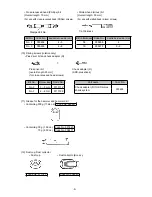
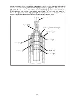
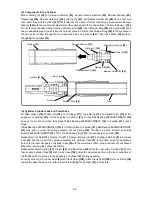
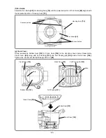
(C) Components in the Cylinder
Mount O-Ring (C)
[22]
on Second Hammer
[23]
, bundle Second Hammer
[23]
, Damper Washer
[24]
,
Damper (B)
[25]
, Damper Holder (A)
[26]
, O-Ring (A)
[27]
, and Damper Holder (B)
[28]
as one unit, and
then insert the unit into Cylinder
[21]
that is laid flat. Then push it further until it stops. Reassemble Damper
Washer
[24]
with the round inner diameter surface aligned with the round surface of Second Hammer
[23]
.
Do not reverse the assembling direction of Damper (B)
[25]
. Insert Stopper Ring
[29]
into Cylinder
[21]
and
use an adequate pipe to push it into the cylinder groove. Confirm that Stopper Ring
[29]
is firmly seated in
the groove by looking through the two inspection holes on Cylinder
[21]
. Then insert Striker
[30]
with O-
Ring
[62]
into Cylinder
[21]
.
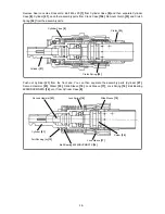
(d) Cylinder, Cylinder Case and Crank Case
Fit Slide Sleeve
[19]
, Washer (B)
[18]
, Lock Sleeve
[17]
, Lock Spring
[16]
, and Washer (A)
[15]
to the
periphery of Cylinder
[21]
. Fit these parts to Cylinder
[21]
so that Ball Bearing 6905DDUCMNS7S
[14]
does not come off, and then fully press-fit Ball Bearing 6905DDUCMNS7S
[14]
to Cylinder
[21]
until it
stops.
If Ball Bearing 6905DDUCMNS7S
[14]
is not firmly fitted to Cylinder
[21]
, Ball Bearing 6905DDUCMNS7S
[14]
may pop up under the spring pressure of Lock Spring
[16]
. Therefore, be sure to firmly push Ball
Bearing 6905DDUCMNS7S
[14]
. Then fit Felt Packing (A)
[13]
to the periphery of Cylinder
[21]
.
Reassemble Oil Seal
[10]
, Damper (A)
[11]
, Damper Washer (B)
[12]
, O-Ring (1AS-50)
[9]
in Cylinder
Case
[8],
and then insert the cylinder assembly into Cylinder Case
[8]
. In this case, align the depressed
portion in the inner periphery of Cylinder Case
[8]
with the projected portion in the periphery of Lock Sleeve
[17]
when inserting the cylinder assembly.
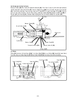
Reassemble Clutch Spring
[32]
, Clutch
[33]
, and Bevel Gear
[34]
from the rear end of Cylinder
[21]
, and
then couple Cylinder Case
[8]
with Crank Case
[104]
. Align the projected portion in the inner periphery of
Clutch
[33]
with the groove in the periphery of Cylinder
[21]
during assembly.
For easy coupling of Cylinder Case
[8]
with Crank Case
[104]
, rotate Crank Shaft
[106]
to move Piston
[36]
toward the upper dead end, and then insert Piston
[36]
into Cylinder
[21]
in this state.
Damper (B)
[25]
Stopper Ring
[29]
Cylinder
[21]
Pipe
Groove
Hole (2 pcs.)
Damper Washer
[24]
Damper Holder (B)
[28]
O-Ring (A)
[27]
O-Ring (C)
[22]
Second Hammer
[23]
Damper Holder (A)
[26]
Cylinder
[21]

