background image

-29-

MODEL


Variable

Fixed

10

20

30

40

50

60 min.

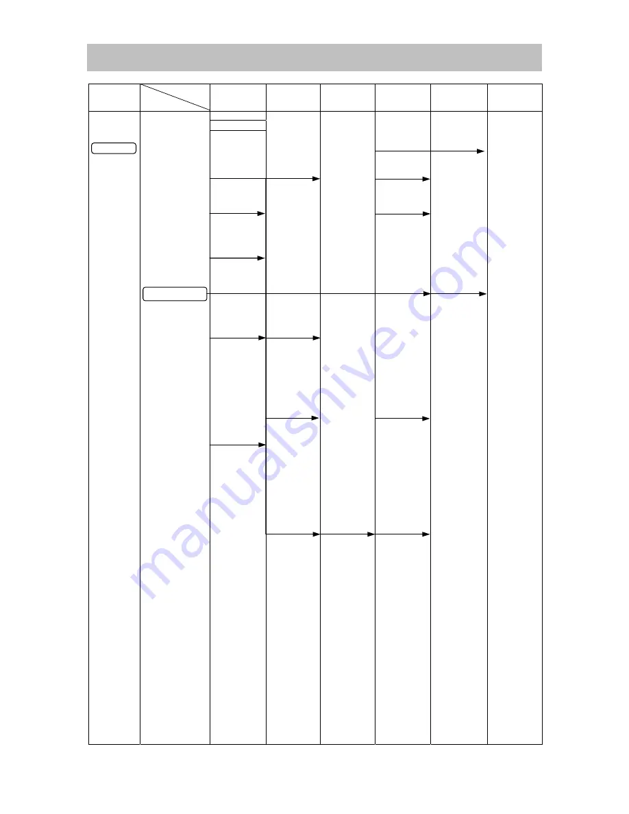
Work Flow

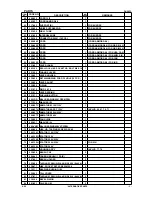
DH 28PC

General Assembly

Tail Cover

Crank Cover
Rubber Seal

Front Cap
Grip
Ball Holder
Holder Plate
Holder Spring

O-ring
Lever Shaft
Lever Holder
Change Lever
Lever Spring
Pushing

Button

Handle (A). (B)

 Set

Switch
Cord
Cord Armor D8.8

Cylinder Case
Oil Seal
Damper (A)
Ball Bearing
6905DDUCMNS7S

Slide Sleeve
Washer (A)
Washer (B)
Lock Spring
Lock Sleeve
Clutch
Clutch Spring

Striker
O-ring

(I.D 19.2) x 2

Second

Hammer

Damper

Washer

Damper (B)
Damper

Holder (A)

Damper

 Holder (B)

Gear Cover

Armature Ass’y
Ball Bearing

6001DDCMPS2L

Ball Bearing

608VVC2PS2L

Crank Shaft
Oil Seal (B)
Ball Bearing

6002DDCMPS2L

O-ring (S-32)
First Gear
Ball Bearing

608VVC2PS2L

Piston
Connecting Rod
Bevel Gear

Slip Clutch

 Ass’y

Bevel Pinion
Oil Seal (B)
Collar
Sleeve
Ball Bearing

6001DDCMPS2L

Second Gear
Ball Bearing

608VVC2PS2L

Cylinder

Housing Ass’y
Stator

Crank Case

STANDARD REPAIR TIME (UNIT) SCHEDULES

Summary of Contents for DH 28PC

Page 1: ...s Rotation Hammering Rotation only and Hammering only that enable chipping and groove cutting work This 3 mode type of product offers improved drilling chipping performance as well as reduced product size and weight This product together with the dust collection type of product DH 28PD developed at the same time forms a continuous lineup of D shaped handle rotary hammer drills in order to promote ...

Page 2: ...ki com manual_view_export Throughout this TECHNICAL DATA AND SERVICE MANUAL a symbol s is are used in the place of company name s and model name s of our competitor s The symbol s utilized here is are as follows Competitors Symbols Utilized Company Name Model Name B BOSCH GBH3 28E C MAKITA HR2811F ...

Page 3: ...WITH SIMILAR PRODUCTS 10 1 Comparison of Specifications 10 2 Comparison of Drilling Speed 11 PRECAUTIONS ON SALES PROMOTION 12 1 Safety Instructions 12 REFERENCE MATERIALS 13 REPAIR GUIDE 17 1 Precautions on Disassembly and Reassembly 17 STANDARD REPAIR TIME UNIT SCHEDULES 29 Assembly Diagram for DH 28PC ...

Page 4: ...mm C 225 mm HITACHI DH 28PC shape Most compact body in its class By downsizing and optimizing the motor and mechanism components Hitachi significantly reduced overall product length to achieve the most compact body in this class of product Model HITACHI DH 28PC C B Full length mm 316 320 332 SELLING POINTS Based on our own research ...

Page 5: ...ion hammering and Rotation and one additional mode of Hammering These modes enables not only light chiseling work using bull points but also heavy work using cold chisels and cutters such as groove digging and cornering work thereby expanding the range of product use The user can easily mount a bit in any of 12 angle positions by simply setting the change lever to the neutral position and turning ...

Page 6: ... with a felt packing in the air passage This passage only allows air pressure to pass and suppresses fluctuations in internal pressure This stabilizes the hammering action and prevents idle striking and the leakage of grease Easy to operate and double molded switch handle and side handle The switch handle and side handle both feature a two layer structure in which the plastic resin molded base is ...

Page 7: ... Materials Nylon resin Handle A B tail cover crank cover Polycarbonate resin Housing Aluminum alloy die casting Crank case cylinder case gear cover Colors Green gray green black Type of switch Variable trigger switch Types of handles D shaped handle and side handle Full load rotation rate min 1 0 800 Full load impact rate min 1 0 4 000 Product 3 5 7 7 Weight Packed kg lbs 6 5 14 3 Packaging Plasti...

Page 8: ...110 50 303577 14 3 260 200 303609 6 0 303579 14 5 166 100 303597 6 4 303580 14 5 260 200 303610 6 5 303581 15 0 303598 7 0 303582 16 0 166 100 303599 7 5 303583 16 0 260 200 303611 8 0 160 100 303584 16 5 303600 8 5 160 100 303585 17 0 166 100 303601 9 0 303586 17 0 260 200 308485 9 5 303587 17 5 166 100 303602 10 0 160 100 303588 17 5 260 200 303612 10 0 260 200 303604 18 0 166 100 303603 10 5 16...

Page 9: ...ength Code No Part name Overall length Code No W 1 4 Anchor setting adapter A W 5 16 Anchor setting adapter A W 3 8 Anchor setting adapter A W 3 8 Anchor setting adapter A 260 260 160 260 302976 302975 303621 302974 W 1 4 Anchor setting adapter B W 5 16 Anchor setting adapter B W 3 8 Anchor setting adapter B W 3 8 Anchor setting adapter B 260 260 160 260 302979 302978 303622 302977 Internal cone t...

Page 10: ...2 982685 c Core bit with guide plate The guide plate is not supplied with 25 mm 1 and 29 mm 1 1 8 outer diameter core bits Outer diameter mm Code No Outer diameter mm Code No 25 1 982672 45 1 3 4 982677 29 1 1 8 982673 50 2 982678 32 1 1 4 982674 65 2 9 16 982679 35 1 3 8 982675 80 3 5 32 982680 38 1 1 2 982676 d Core bit shank SDS plus shank Part name Overall length Code No 105 mm 4 1 8 303625 Co...

Page 11: ...ews rotation only Drill chuck chuck adapter G special screw and chuck wrench Special screw 13 mm 1 2 Drill chuck Chuck adapter G 13VLRB D SDS plus shank Chuck wrench NOTE When using the tool to loosen screws open the three jaws of the drill chuck and securely fix the drill chuck to chuck adapter G with the special screw a left hand threaded M6 screw for mounting the drill chuck onto chuck adapter ...

Page 12: ...ews rotation only Plus driver bit and chuck adapter D Plus driver bit Chuck adapter D overall length 25 mm SDS plus shank for cross recessed head screws Bit No Screw size Code No Part name Code No No 2 3 5 mm 971511Z No 3 6 8 mm 971512Z Chuck adapter D for SDS plus shank system 303624 11 Grease for the hammer and hammer drill Containing 500 g 17 64 oz Code No 980927 Containing 30 g 1 06 oz Code No...

Page 13: ...1 0 4 000 0 4 500 No load 0 4 000 Impact energy J 3 5 2 9 3 3 No load noise level measured dB A 85 4 86 3 87 2 Full load noise level measured dB A 87 9 88 8 86 2 Full load vibration level Tri axial measured m s2 20 7 20 1 27 4 Length 316 12 7 16 320 12 5 8 332 13 1 16 Height 208 8 3 16 225 8 55 64 208 8 3 16 Tool size Width mm 102 4 89 3 1 2 93 3 21 32 Weight kg lbs 3 5 7 7 3 2 7 0 3 3 7 3 Mode 3 ...

Page 14: ...lts shown in the figure below for comparison purposes only Test conditions Direction Downward drilling Pushing force 98 N 10 kgf Test material Concrete panel with compression strength of 2 352 N cm2 240 kgf cm2 0 100 200 300 400 500 600 700 10 12 14 16 18 20 22 24 26 28 Drill Bit Dia mm Drilling Speed mm min HITACHI DH28PC C B HITACHI DH30PC2 HITACHI DH25PB ...

Page 15: ...n the use of any electric tool cannot be completely eliminated Accordingly the Handling Instructions list general precautions and suggestions on the use of electric power tools and specific precautions and suggestions on the use of rotary hammers to enhance the safe efficient use of the tool by customers Salespersons must be thoroughly familiar with the Handling Instructions in order to offer appr...

Page 16: ...tion inside the gear cover uses Hitachi Motor Grease No 29 The proper amount of grease is 15 g Never use the special grease for the hammering section in the gear change section Otherwise the special grease will leak into the motor section and cause subsequent trouble Periodically change the grease in the slip clutch Fully fill the slip clutch with Cosmos Molybdenum Grease No 2 2 Structure of the M...

Page 17: ...ween the piston and striker Changes in air pressure inside the air chamber cause the striker to move Hammering force is thus transmitted to the second hammer and then to the bit tool Hammering only Set the change lever to the Hammering only mark position The bevel gear disengages from the clutch to cut off the transmission of rotational force The spline in the inner periphery of the lock sleeve en...

Page 18: ...nsmitted Neutral This product has a Neutral mode to be used to determine the working position of a bit tool such as a cold chisel Set the change lever to the Neutral mark position The bevel gear disengages from the clutch and cuts off the transmission of rotational force The lock sleeve also disengages from the clutch so that the cylinder can rotate freely In this state the user can turn a bit too...

Page 19: ...king operation 3 Mechanism to prevent idle hammering 4 Slip clutch mechanism 5 Sealing and dust proof structure 6 Speed control 7 Handle and side handle 8 Caution when using Rotation only No hammering function 9 Drill bits 10 Tool retainer 11 Dust collector B DH 24PC2 No E479 DH 24PC3 No E489 DH 30PC2 No E494 ...

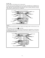
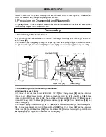
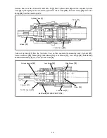
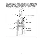
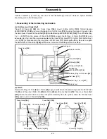
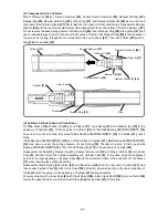
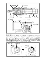
Page 20: ...r 21 2 Disassembly of the hammering mechanism a Cylinder Case and Cylinder First remove Seal Lock Hex Socket Hd Bolt M4 x 12 57 from Change Lever 58 and then demount Change Lever 58 and Lever Holder 59 Remove Hex Socket Hd Bolt W Flange M4 x 10 43 Hex Socket Hd Bolt W Flange M5 x 16 98 Tapping Screw W Flange D5 X 20 Black 78 and Tapping Screw W Flange D4 X 25 Black 44 Remove Handle A B Set 40 from...

Page 21: ...y parts Push out Cylinder 21 from the front end You can then separate the assembly parts Cylinder 21 Second Hammer 23 Striker 30 Slide Sleeve 19 Lock Sleeve 17 Lock Spring 16 Ball Bearing 6905DDUCMNS7S 14 etc from Cylinder Case 8 Cylinder Case 8 Cylinder 21 Clutch 33 Clutch Spring 32 Cylinder 21 Second Hammer 23 Striker 30 Slide Sleeve 19 Lock Sleeve 17 Lock Spring 16 Ball Bearing 6905DDUCMNS7S 14...

Page 22: ...end face of Cylinder 21 and then demount Ball Bearing 6905DDUCMNS7S 14 You can then separate Washer A 70 Lock Spring 16 Lock Sleeve 17 Washer B 67 and Slide Sleeve 19 Cylinder 21 and other parts may pop up under spring pressure when you demount Ball Bearing 6905DDUCMNS7S 14 Therefore be very careful Hook of bearing puller Ball Bearing 6905DDUCMNS7S 14 Washer A 70 Cylinder 21 Hand press Lock Sleeve...

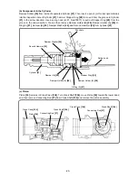
Page 23: ... then remove Damper Holder B 28 Damper Holder A 26 O Ring A 27 Damper B 25 Damper Washer 24 and Second Hammer 23 from Cylinder 21 c Piston Piston 36 remains in Crank Case 104 Turn Crank Shaft 106 move Piston 36 toward the lower dead end then remove Connecting Rod 37 from Crank Shaft 106 and remove the piston assembly Cylinder 21 Punch etc Stopper Ring 29 Spring hook Second Hammer 23 Damper Washer ...

Page 24: ...rank Case 104 on an adequate tool rest with its Connecting Rod 37 side facing downward then use an adequate steel rod and a hand press to push the end of Crank Shaft 106 Crank Shaft 106 First Gear 111 and Ball Bearing 608VVC2PS2L 96 then come off Crank Case 104 First Gear 111 Crank Shaft 106 Ball Bearing 608VVC2PS2L 96 Suitable steel bar Work bench Hand press ...

Page 25: ...3 x 3 x 8 107 is firmly seated in the key groove of First Gear 111 before press fitting Be sure to support the flat surface of Crank Shaft 106 with the steel rod since the abutting surface has steps b Piston Remount O Ring I D 19 2 31 on Piston 36 apply a small amount of power tool grease No 29 to Piston Pin 35 and then insert Piston Pin 35 into Piston 36 and Connecting Rod 37 Then move Crank Shaf...

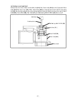
Page 26: ...until it stops If Ball Bearing 6905DDUCMNS7S 14 is not firmly fitted to Cylinder 21 Ball Bearing 6905DDUCMNS7S 14 may pop up under the spring pressure of Lock Spring 16 Therefore be sure to firmly push Ball Bearing 6905DDUCMNS7S 14 Then fit Felt Packing A 13 to the periphery of Cylinder 21 Reassemble Oil Seal 10 Damper A 11 Damper Washer B 12 O Ring 1AS 50 9 in Cylinder Case 8 and then insert the ...

Page 27: ...Lever 58 along with Lever Spring 64 Pushing Button 65 and Pin D2 x 10 63 at the Rotation hammering position Press Pushing Button 65 of Change Lever 58 and confirm that Pin D2 x 10 63 of Change Lever 58 is firmly seated in the groove of Lever Holder 59 Then tighten Seal Lock Hex Socket Hd Bolt M4 x 12 57 Crank Case 104 Piston 36 Connecting Rod 37 Crank Shaft 106 Cylinder Case 8 Bevel Gear 34 Clutch...

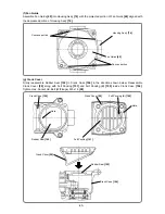
Page 28: ...eal 102 in Crank Case 104 in the direction shown below Reassemble Crank Cover 99 along with Felt Packing 101 and Felt Packing B 100 inside Crank Case 104 Tighten Hex Socket Hd Bolt W Flange M5 x 16 98 Housing Ass y 74 Fan Guide 69 Concave portion Convex portion Crank Case 104 Rubber Seal 102 Hole Crank Cover 99 Felt Packing 101 Felt Packing B 100 Hole Rubber Seal 102 Crank Case 104 Crank Cover 99 ...

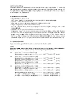
Page 29: ... 62 the outer diameter portion of Lock Sleeve 17 the slide portions of Second Hammer 23 and Striker 30 the inner diameter portions of Slide Sleeve 19 and Clutch 33 and both the inner and outer diameter portions of Bevel Gear 34 3 Tightening torque Apply screw locking agent TB1401 to all hex socket head bolts M4 M5 and M6 NOTE Be sure to apply screw locking agent Three Bond TB1401 to the threads du...

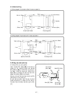
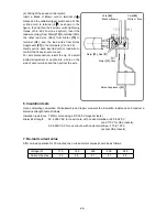
Page 30: ...terminal 4 Gently pull on each inserted lead wire to confirm that the wires do not come out For wire disconnection insert the tip of a small slotted screwdriver or needle into the hole on the side of each terminal and then pull out the wire Cord Stator Stator Armature Speed control switch Reversing switch Black or Brown White or Blue Gray White Lead wire Brown Lead wire Blue Black Red Noise suppre...

Page 31: ...rewdriver or needle into a hole on the side of each terminal and then pull out the wire 6 Insulation tests Upon completing completion of disassembly and repair measure the insulation resistance and conduct a dielectric strength test as follows Insulation resistance 7 Mȍ or more using a DC 500 V megohm tester Dielectric strength AC 4 000 VAC for one minute with no abnormalities 220 to 240 V and 110...

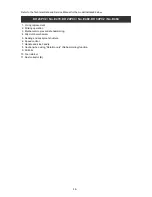
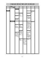
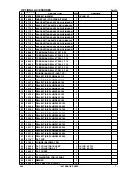
Page 32: ...asher A Washer B Lock Spring Lock Sleeve Clutch Clutch Spring Striker O ring I D 19 2 x 2 Second Hammer Damper Washer Damper B Damper Holder A Damper Holder B Gear Cover Armature Ass y Ball Bearing 6001DDCMPS2L Ball Bearing 608VVC2PS2L Crank Shaft Oil Seal B Ball Bearing 6002DDCMPS2L O ring S 32 First Gear Ball Bearing 608VVC2PS2L Piston Connecting Rod Bevel Gear Slip Clutch Ass y Bevel Pinion Oil...

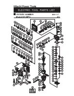
Page 33: ...2 33 34 35 36 37 56 57 58 61 62 63 59 60 64 65 66 67 68 70 71 72 73 74 75 76 77 79 78 80 81 82 83 84 85 86 87 88 89 90 93 94 95 96 97 98 99 102 103 98 104 106 108 109 110 111 96 40 43 44 42 41 47 48 49 38 39 50 51 45 46 52 53 107 69 31 39 54 55 501 502 503 504 505 506 507 508 509 510 17 18 19 20 21 91 92 112 87 96 83 85 12 13 26 28 100 101 105 27 89 89 ...

Page 34: ...R B 1 26 331 672 DAMPER HOLDER A 1 27 330 186 O RING A 1 28 331 673 DAMPER HOLDER B 1 29 323 062 STOPPER RING 1 30 330 185 STRIKER 1 31 319 577 O RING I D 19 2 2 32 330 188 CLUTCH SPRING 1 33 330 189 CLUTCH 1 34 330 190 BEVEL GEAR 1 35 330 173 PISTON PIN 1 36 330 172 PISTON 1 37 319 585 CONNECTING ROD 1 38 NAME PLATE 1 39 886 342 HITACHI PLATE 2 40 330 256 HANDLE A B SET 1 41 331 677 SWITCH 1 41 3...

Page 35: ...5 O RING 1 63 321 312 PIN D2 X 10 1 64 321 310 LEVER SPRING 1 65 321 311 PUSHING BUTTON 1 66 600 1DD BALL BEARING 6001DDCMPS2L 1 67 971 736 WASHER B 1 68 360 857C ARMATURE 110V 115V 1 68 360 857U ARMATURE ASS Y 120V 1 INCLUD 66 67 70 71 68 360 857E ARMATURE 220V 230V 1 68 360 857F ARMATURE 240V 1 69 330 202 FAN GUIDE 1 70 982 631 WASHER A 1 71 608 VVM BALL BEARING 608VVC2PS2L 1 72 980 864 HEX HD T...

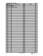
Page 36: ...2L 2 97 330 200 GEAR COVER 1 98 994 192 HEX SOCKET HD BOLT W FLANGE M5 X 16 6 99 330 204 CRANK COVER 1 100 324 544 FELT PACKING B 1 101 331 674 FELT PACKING 1 102 331 675 RUBBER SEAL 1 103 324 060 SEAL LOCK HEX SOCKET HD BOLT M5 X 40 4 104 330 169 CRANK CASE 1 105 331 676 SEAL PACKING 1 106 330 170 CRANK SHAFT 1 107 944 109 FEATHER KEY 3 X 3 X 8 1 108 600 2DD BALL BEARING 6002DDCMPS2L 1 109 872 76...

Page 37: ...8 SIDE HANDLE ASS Y 1 INCLUD 504 510 504 330 209 SIDE HANDLE 1 505 307 947 WING BOLT M6 X 12 1 506 330 210 MOUNT 1 507 949 556 NUT M6 10 PCS 1 508 330 212 BAND 1 509 330 211 BOLT HOLDER 1 510 330 213 BOLT M8 X 45 1 9 09 5 ALTERNATIVE PARTS STANDARD ACCESSORIES NO USED CODE NO ITEM NO ...

Page 38: ...CHUCK ADAPTER D SDS PLUS 1 623 321 825 DRILL CHUCK AND ADAPTER SET 1 INCLUD 624 625 624 303 623 CHUCK ADAPTER G SDS PLUS 1 625 321 814 DRILL CHUCK 13VLRB D 1 INCLUD 626 626 995 344 FLAT HD SCREW A LEFT HAND M6 X 25 1 627 321 813 DRILL CHUCK 13VLD D 1 628 980 927 GREASE FOR HAMMER HAMMER DRILL 500G 1 629 981 840 GREASE A FOR HAMMER HAMMER DRILL 30G 1 630 308 471 GREASE FOR HAMMER HAMMER DRILL 70G 1...

Page 39: ...ILL BIT SDS PLUS D5 0 X 110 1 673 303 578 DRILL BIT SDS PLUS D5 0 X 160 1 674 303 576 DRILL BIT SDS PLUS D5 5 X 110 1 675 303 581 DRILL BIT SDS PLUS D6 5 X 160 1 676 303 582 DRILL BIT SDS PLUS D7 0 X 160 1 677 303 584 DRILL BIT SDS PLUS D8 0 X 160 1 678 303 585 DRILL BIT SDS PLUS D8 5 X 160 1 679 303 586 DRILL BIT SDS PLUS D9 0 X 160 1 680 303 591 DRILL BIT SDS PLUS D12 0 X 160 1 681 303 606 DRILL...

Page 40: ...DH 28PC DESCRIPTION REMARKS 701 986 805 OUTER RACE 1 702 986 806 SOCKET 1 703 306 910 SOCKET ADAPTER B 1 8 Printed in Japan 9 09 090907N OPTIONAL ACCESSORIES ALTERNATIVE PARTS NO USED CODE NO ITEM NO ...

Reviews: