--- 25 ---
9-2. Reassembly
Reassembly can be accomplished by following the disassembly procedures in reverse. However, special
attention should be given to the following items.
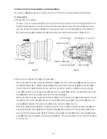
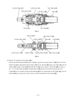
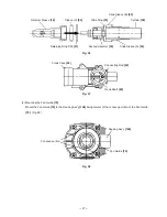
(1) Mouting the First Gear
[98]
and the Crank Shaft
[92]
Press-fit Oil Seal (B)
[75]
in the Crank Case
[94]
then the O-ring (S-32)
[96]
is fitted in the groove inside the
Crank Case
[94]
. Press-fit the Ball Bearing 6002DDCMPS2L
[95]
in the Crank Case
[94]
then the Retaining
Ring for D32 Hole
[97]
is fitted in the groove inside the Crank Case
[94]
. Press-fit the Crank Shaft
[92]
in the
Ball Bearing 6002DDCMPS2L
[95]
. Put the Feather Key 3 x 3 x 8
[93]
into the groove of the Crank Shaft
[92]
and press-fit the First Gear
[98]
with a suitable tool while holding the flat portion of the Crank Shaft
[92]
with a
steel bar. Before press-fitting, make sure that the Feather Key 3 x 3 x 8
[93]
fits in the key groove of the First
Gear
[98]
. (Fig. 21)
Fig. 21
First Gear
[98]
Crank Case
[94]
Suitable tool
Feather Key 3 x 3 x 8
[93]
O-ring (S-32)
[96]
Retaining Ring for D32 Hole
[97]
Ball Bearing 6002DDCMPS2L
[95]
Oil Seal (B)
[75]
Crank Shaft
[92]
Suitable steel bar
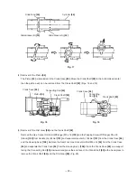
(2) Mouting the Piston
[44]
Mount the O-ring (I.D 19.2)
[32]
to the Piston
[44]
. Insert the Piston Pin
[43]
into the Piston
[44]
and the
Connecting Rod
[45]
. Move the Crank Shaft
[92]
to the bottom dead center then insert the piston ass'y into the
Crank Case
[94]
from the Cylinder Case
[9]
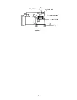
side. (Figs. 22 and 23)
Piston
[44]
Crank Case
[94]
Crank Shaft
[92]
Connecting Rod
[45]
Fig. 22
Crank Case
[94]
Crank Shaft
[92]
Connecting
Rod
[45]
Fig. 23
O-ring
[32]
Piston Pin
[43]


