--- 14 ---
9. REPAIR GUIDE
The numbers in [Bold] correspond to the item numbers in the Parts List and exploded assembly diagrams.
9-1. Disassembly
Knob (A) [3]
Needle Roller D4 x 20 [4]
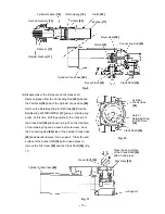
Fig. 8
(1) Disassembly of the tool holder
Disassembly procedures are illustrated in Fig. 8. Pull Knob (A) [3] outward in the direction indicated by the
arrow, and turn it slightly so that its end surface comes to rest on the flange portion of the Front Cover [5].
Push in the Stop Washer [1] with two flat-blade screwdrivers to compress the Stopper Spring [2], and insert a
steel rod (less than 3 mm in diameter) into the 3 mm diameter hole in Knob (A) [3] to push out the Needle
Roller D4 x 20 [4]. The Stop Washer [1], Stopper Spring [2], Stop Lever [7] and Knob (A) [3] can then be
taken off.
Slide the end surface of Knob (A) [3] onto the flange of the Front Cover [5]
Stop Lever [7]
Front Cover [5]
Stopper Spring [2]
Push in the Stop Washer
[1] with two flat-blade
screwdrivers.
3 mm dia. or less steel bar
Stop Washer [1]
3 mm dia. hole
(2) Disassembly of the piston and the striker
Remove the Seal Lock Hex. Socket Hd. Bolt M4 x 12 [28] from the Crank Cover [30] then remove the Crank
Cover [30] from the Cylinder Crank Case [40]. Remove the Seal Lock Hex. Socket Hd. Bolt M6 x 45 [27] and
Seal Lock Hex. Socket Hd. Bolt M6 x 22 [82]. Remove the Gear Cover [57] from the Cylinder Crank Case
[40]. Remove the Bevel Pinion [41] (slip clutch) from the Cylinder Crank Case [40] (otherwise, Bevel Gear
[26] cannot be removed later). Remove the Seal Lock Hex. Socket Hd. Bolt M4 x 12 [63] from the Change
Lever [64] then remove the Change Lever [64]. Remove the Retaining Ring for D20 Hole [66] using a
retaining ring puller and remove the Lever Shaft [67] (otherwise, Bevel Gear [26] cannot be removed later).
Remove the Seal Lock Hex. Socket Hd. Bolt M6 x 25 [6] from the Front Cover [5]. Then the Front Cover [5],
Second Hammer [10], Damper Washer [11], Damper [12], Cylinder Washer [18], Clutch Spring [19], Clutch
[22], Cylinder [17], etc. can be removed from the Cylinder Crank Case [40] in an assembly state. Remove the
Bevel Gear [26] from the Cylinder Crank Case [40] by tapping the Front Cover [5] side with a plastic hammer.
Remove the Striker [20] from the Cylinder [17] by tapping with a plastic hammer. The Piston [23] remains in
the Cylinder Crank Case [40]. Remove the Retaining Ring for D10 Shaft [33] using a retaining ring puller and
remove the Connecting Rod [25] from the Crank Shaft [34] (Fig. 9).
Summary of Contents for DH 40FR
Page 30: ......


