-6-
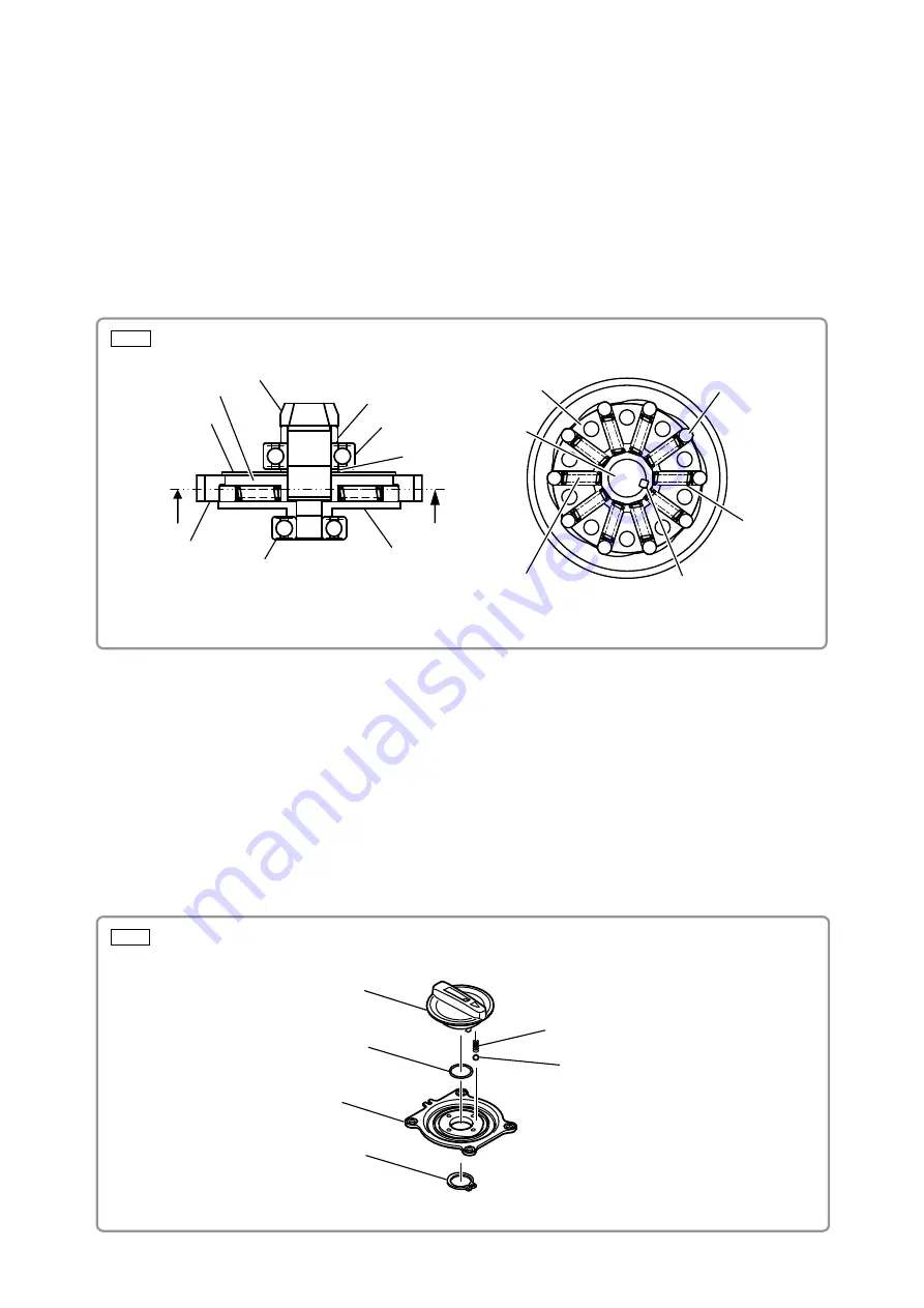
Fig. 10 • Reassembly of the slip clutch ass'y
Fig. 11 • Mounting the lever shaft holder
[112]
[116]
[113]
[114]
[115]
[118]
(4) Reassembly of the slip clutch ass’y
• Press-fit the Collar
[96]
and Ball Bearing 6002DD
[98]
in this order to the Bevel Pinion
[94]
, and then
insert the Washer
[99]
and Washer (A)
[100]
in this order.
• Mount the Feather Key 3 x 3 x 8
[95]
to the Bevel Pinion
[94]
and press-fit the Gear Holder
[102]
.
• Insert the Second Gear
[101]
into the outer periphery of the Gear Holder
[102]
. Apply Hitachi Motor
Grease No. 29 to the inner periphery of the Second Gear
[101]
in advance.
• Insert the ten Needles
[104]
upright as shown below, and then push in ten Springs (C)
[103]
.
• Fill up the slotted groove and through-hole portions of the Gear Holder
[102]
with Hitachi Motor Grease
No. 29, and then press-fit the Spacer
[105]
and Ball Bearing 629VV
[106]
to the Bevel Pinion
[94]
in
this order.
(5) Mounting the lever shaft holder
• Apply Hitachi Motor Grease No. 29 to the O-ring (S-18)
[115]
, and then attach the O-ring to the Change
Lever
[112]
. Insert the Lever Spring
[113]
into the change lever hole.
• Apply Hitachi Motor Grease No. 29 to the Steel Ball D4.76
[114]
and place it into the concave portion of
the Lever Shaft Holder
[116]
.
• Position the Lever Spring
[113]
and Steel Ball D4.76
[114]
properly. Insert the Change Lever
[112]
into
the hole of the Lever Shaft Holder
[116]
and fix it with the Retaining Ring for D20 Shaft
[118]
.
NOTE: Rotate the Change Lever [112] to check that the lever clicks at each mode position.
Insert the Change Lever [112] into the Lever Shaft Holder [116] straight to avoid
damaging the O-ring.
[94]
[100]
[101]
[106]
[105]
[98]
[96]
[94]
[101]
[104]
[103]
[95]
A
A
Slotted groove in
the gear holder
Section A—A
[99]
[102]


