-12-
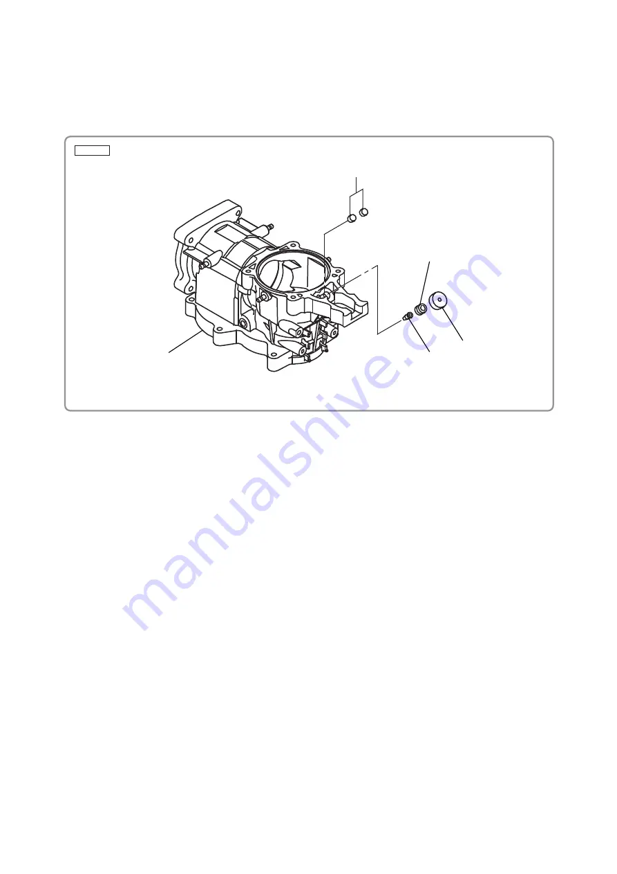
Fig. 17
(8) Reassembly of the valve and felt
Make sure the Valve [111] is inserted in the Crank Case [89]. Grease will leak without the Valve [111].
After inserting the Valve [111], lock it with the Cap Screw [110]. Degrease the felt attaching portion of
the Crank Case [89], and then attach Felt (A) [109] with the hole on Felt (A) [109] matching the hole
on the Cap Screw [110]. Insert two Felts (B) [106] into the hole on the Crank Case [89].
2. Reassembly of the power supply unit
(1) Rotor ass’y
Before inserting the Rotor [134] into the Housing [48], mount the Rotor [134] on the Gear Cover [130].
Without the gear cover, the Rotor [134] will be strongly attracted and fixed to the Stator Sensor PCB
Set [42] by its own magnetic force. Be careful not to let your hand be suddenly pulled by the magnetic
force of the Rotor [134].
(2) Wiring of the controller set (See Fig. 18.)
• Connect the terminals of the three internal wires (red, white, and black) coming from the Stator
Sensor PCB Set [42] to the Controller Set [49] terminals of the same colors. Insert each terminal into
the mating terminal securely until it contacts the innermost end.
• Connect the 5-wire connector of the Stator Sensor PCB Set [42] to the Controller Set [49] connector.
Do not reverse the connector orientation.
• Connect the 8-wire connector of the Panel [112] to the Controller Set [49] connector. Do not reverse
the connector orientation.
(3) Wiring of the filter PCB set (See Fig. 18.)
• Connect the two terminal-equipped internal wires of the Controller Set [49] with those of the Filter
PCB Set [58]. The internal wires can be connected in any order. Insert each terminal into the mating
terminal securely until it contacts the innermost end.
• Connect the two core-exposed internal wires of the Filter PCB Set [58] to Pillar Terminal (A) [67].
[106]
[109]
[110]
[111]
[89]


