-8-
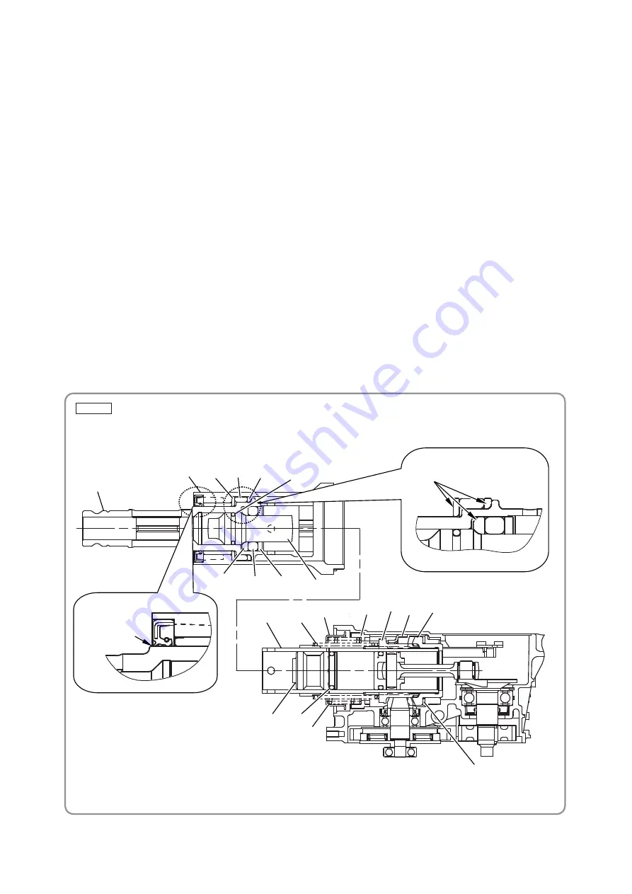
Fig. 10
(3) Cylinder and retainer sleeve
Mount the Retainer Damper Washer [17], Retainer Damper (B) [16], and the Retainer Damper Holder
[15] in this order to the Retainer Sleeve [19] with the rounded surface of the Retainer Damper Washer
[17] facing that of the Retainer Sleeve [19] and the rounded surface of the Retainer Damper Holder
[15] facing that of the Retainer Sleeve [19].
Insert the Second Hammer [21] (equipped with O-ring (C) [20]), Damper Washer [22], Damper [23],
and Damper Holder [24] in this order with the rounded surface of the Damper Washer [22] facing that
of the Second Hammer [21].
Insert the assembled Retainer Sleeve [19] into the Cylinder Case [13]. Be careful not to curl the lip of
the oil seal.
Insert the Slider [33] into the outer periphery of the Bevel Gear [34] along the Crank Case [89] groove.
As shown below, push in the Slider [33] until its stopper contacts the butting position of the Crank Case
[89]. Insert so that the Clutch [32] engages with the internal claw of the Bevel Gear [34].
Insert the Striker [26] equipped with the O-ring [27] into the Cylinder [25]. Fit the Clutch Spring [31] to
the Cylinder [25], and then insert the assembled Cylinder [25] into the Crank Case [89].
Next, insert the Lock Sleeve [30] into the Crank Case [89] with the inner spline groove of the Crank
Case [89] matched with the Lock Sleeve [30] spline. Then place the Lock Spring [29] and Spring
Holder (B) [28] on the Lock Sleeve [30].
Finally, fit the protrusion of the Retainer Sleeve [19] to the Cylinder [25] groove, and then assemble the
Cylinder Case [13] equipped with the Retainer Sleeve [19] with the Crank Case [89] equipped with the
Cylinder [25].
[19]
[13]
[15]
[16]
[17]
[24]
[23]
[22]
[25]
[31]
[28]
[30] [32] [33] [34]
[26]
[29]
[35]
Note directions of [15],
[17], and [22].
[21]
[27]
[20]
Do not curl the
oil seal lip.


