


Summary of Contents for DH 40MRY
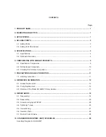
Page 39: ......
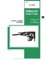
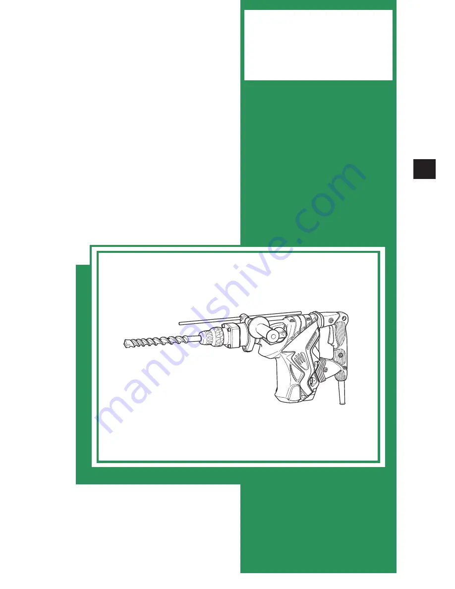
The Hitachi DH 40MRY is a powerful rotary hammer with impressive drilling capabilities. To ensure proper usage and maintenance, it comes with a comprehensive Technical Data And Service Manual. Users can conveniently download this manual for free from 88.208.23.73:8080, empowering them with the necessary knowledge to optimize the tool's performance.
Page 39: ......