


-13-
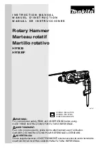
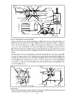
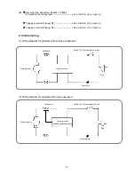
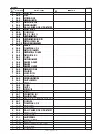
Fig. 3
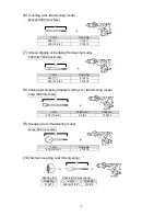
(d) First Gear
[116]
and Crank Shaft
[79]
Remove the Seal Lock Hex. Socket Hd. Bolt M6 x 45
[114]
, Seal Lock Hex. Socket Hd. Bolt M6 x 22
[122]
, Seal Lock Hex. Socket Hd. Bolt M5 x 30
[90]
, Seal Lock Hex. Socket Hd. Bolt M5 x 16
[67]
, Hex.
Socket Hd. Bolt (W/Flange) M5 x 14
[54]
and Tapping Screw (W/Flange) D5 x 30 (Black)
[63]
and
remove the Crank Case
[115]
from the Housing Ass'y
[136]
, Back Cover
[53]
and Handle (A). (B) Set
[56]
. (Note that the Gear Cover
[113]
and the Crank Case
[115]
cannot be removed without removing the
Seal Lock Hex. Socket Hd. Bolt M5 x 30
[90]
and separating the weight ass'y from the Crank Case
[115]
.)
Remove grease from the Piston
[35]
side and the First Gear
[116]
side of the Crank Case
[115]
.
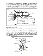
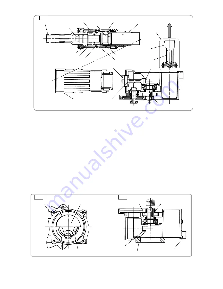
Remove the Retaining Ring for D47 Hole
[81]
fixing the Ball Bearing 6204DDCMPS2L
[82]
with a
retaining ring puller. At this time, turn the Crank Shaft
[79]
so that the hole of the Retaining Ring for
D47 Hole
[81]
can be seen before removal (Fig. 4). Press the end face of the Crank Shaft
[79]
with
a hand press to remove the First Gear
[116]
, Second Pinion
[117]
and Crank Shaft
[79]
from the
Crank Case
[115]
(Fig. 5).
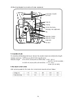
Fig. 4
Fig. 5
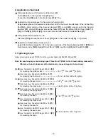
(e) Slip Cluch
Refer to the Technical Data and Service Manual for the Model DH 50MB (List No. E455) because the slip
clutch mechanism is the same as that of the Model DH 50MB.
Retainer Sleeve
[19]
Second Hammer
[21]
Cylinder
[26]
Lock Spring
[27]
Clutch Spring
[30]
Striker
[31]
Cylinder Case
[37]
Spring Holder (B)
[29]
Needle Pin D8 x 6
[25]
Damper Holder
[24]
Damper
[23]
Piston
[35]
Retaining Ring for D12 Shaft
[78]
Connecting Rod
[36]
Crank Shaft
[79]
Damper Washer
[22]
Weight ass’y
Weight
[88]
Leaf Spring
[93]
Crank Shaft
[79]
Retaining Ring For D47 Hole
[81]
Crank Case
[115]
Crank Case
[115]
Crank Shaft
[79]
First Gear
[116]
Support
Second Pinion
[117]