


--- 21 ---
9. PRECAUTIONS IN DISASSEMBLY AND REASSEMBLY
The numbers in
[Bold]
correspond to the item numbers in the Parts List and exploded assembly diagrams.
9-1. Disassembly
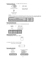
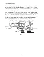
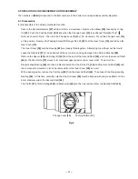
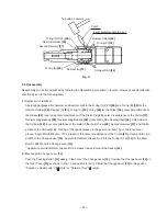
(1) Disassembly of the striking mechanism section
Push in the Second Hammer
[27]
with a drill bit or a screwdriver. Remove the Striker
[35]
chucked by O-ring
(C)
[32]
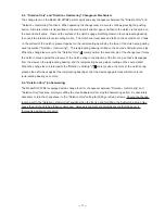
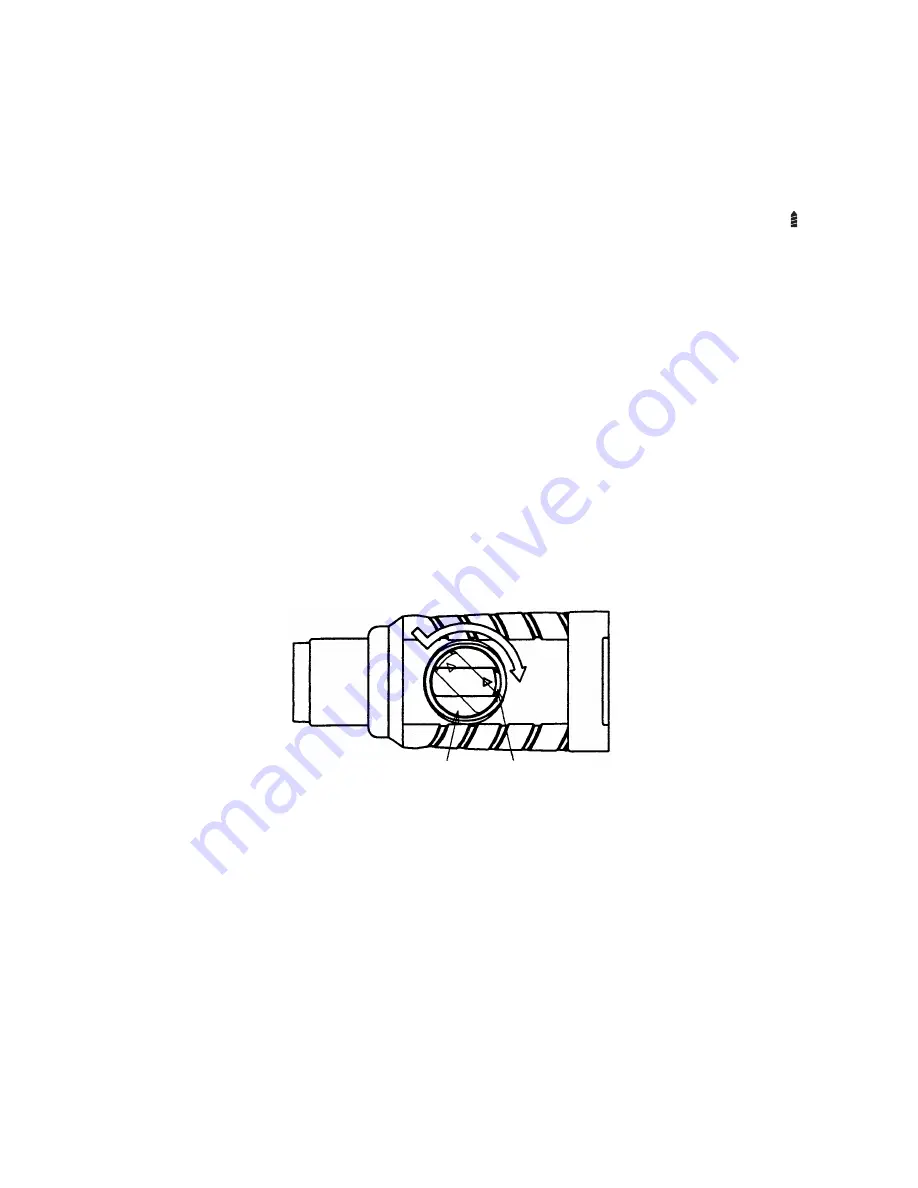
. Push the Pushing Button
[12]
fully when the Change Lever
[14]
is positioned "Rotation Only" (
mark) as shown in Fig. 8. Then turn the Change Lever
[14]
by 135
û
clockwise. Ply out the Change Lever
[14]
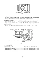
at this position. Remove the Tapping Screw (W/Flange) D5 x 35
[9]
from the Gear Cover
[10]
and remove the
Gear Cover
[10]
.
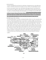
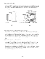
The Inner Cover
[39]
and the Housing
[62]
are loosely fitted together. Attempting to pull them out first could
cause the Armature
[57]
to be pulled out at the same time, causing damage to the Carbon Brushes
[66]
.
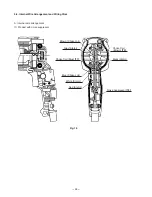
Remove the Spacer
[42]
and Spring (B)
[43]
from the end of the Second Shaft
[44]
, and turn the Second Shaft
[44]
so that the Piston
[37]
moves to its maximum upper position (inner cover side). The arm of the
Reciprocating Bearing
[48]
can then be disconnected from the Piston Pin
[40]
, and the Second Shaft
[44]
and
the components mounted on it can be removed from the Inner Cover
[39]
as a unit.
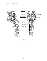
With a bearing puller, remove the First Gear
[49]
from the Second Shaft
[44]
. Then take off the Reciprocating
Bearing
[48]
. At this time, carefully note that the First Gear
[49]
must be aligned with and press-fitted onto the
9 mm diameter end of the Second Shaft
[44]
.
The Clutch
[47]
, Clutch Spring
[46]
and Washer (B)
[45]
can then be removed from the Second Shaft
[44]
.
Fig. 8
Change Lever
[14]
Pushing Button [
12]
Summary of Contents for DH24PB2
Page 39: ......