--- 15 ---
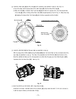
(h) Install the Shift Arm [19] into the assembly reassembled in step (g).
With the ridge at the Shift Arm [19] facing the Motor [28] side, first install them on the unmarked side of the
assembly reassembled in step (g). Then insert the projections on the Shift Arm [19] into the holes in the
Rear Case [17] and make sure that the projections are fitted into the grooves in the Slide Ring Gear [20]
mounted within the Rear Case [17]. (See Fig. 13.)
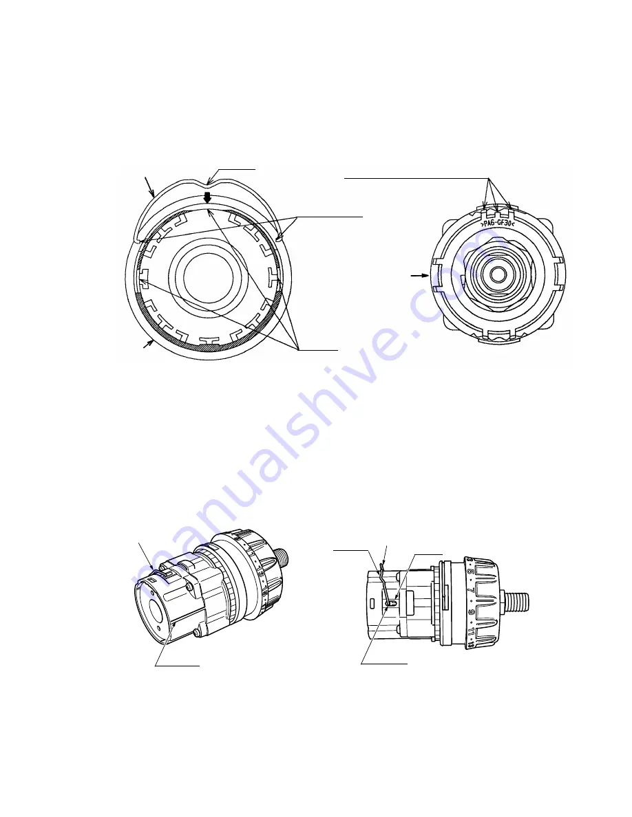
(g) Install the Click Spring [5] and the Cap [4] to the assembly reassembled in step (f). (See Fig. 12.)
(i) Insert the ridge and the projections of the Click Spring [5] into the holes of the Cap [4].
(ii) When the Nut [6] is screwed in the Front Case [9] about one and a quarter turns, the three projections
of the Nut [6] and the marking of the Rear Case [17] are positioned as shown in Fig. 12. Mount the Cap
[4] aligning the ridge of the Click Spring [5] with the three projections of the Nut [6].
Fig. 12
Click Spring [5]
Marking of the
Rear Case [17]
Holes
Ridge
Three projections of the Nut [6]
Cap [4]
Projections
Fig. 13
[19]
Ridge
[19]
Hole
Groove
Mark
(i) Install the Drill Chuck 13VLRG-N (W/O Chuck Wrench) [2].
Install the Drill Chuck 13VLRG-N (W/O Chuck Wrench) [2] using a socket wrench 19 mm, etc. and secure
it with the Special Screw (Left Hand) M6 x 23 [1].


