


12
5
.
How
to
select
tightening
torque
and
rotational
speed
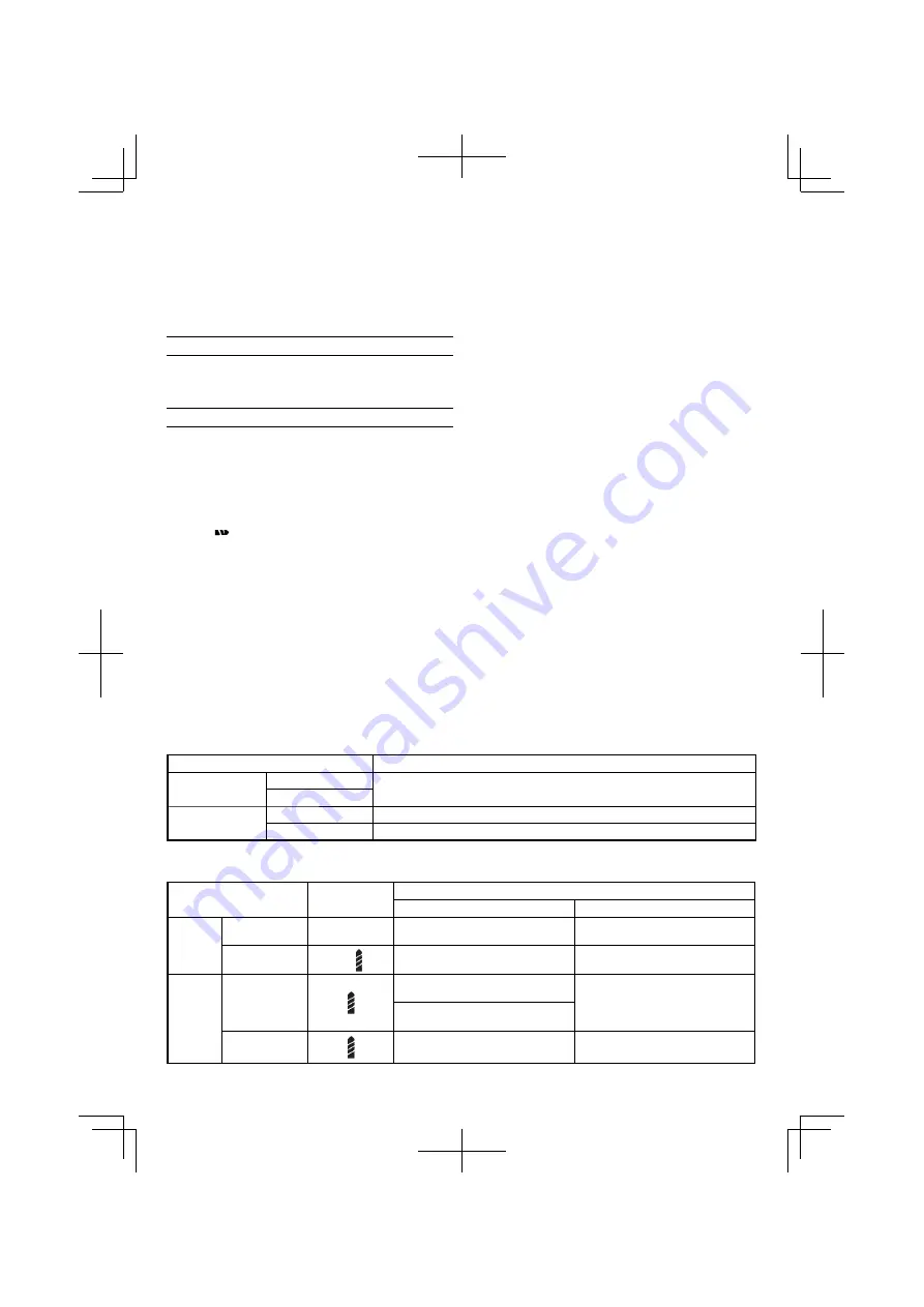
Table
4
Use
Clutch Dial
Position
Rotating speed selection (Position of the shift knob)
LOW (Low speed)
HIGH (High speed)
Driving
Machine screw
1 – 21
For 6 mm or smaller diameter
screws
.
For 6 mm or smaller diameter
screws
.
Wood screw
1 –
For 5
.
8 mm or smaller nominal
diameter screws
.
For 3
.
8 mm or smaller nominal
diameter screws
.
Drilling
Wood
For 25 mm or smaller diameters
.
(DS12DVC)
For 12 mm or smaller diameters
.
For 21 mm or smaller diameters
.
(DS9DVC)
Metal
For drilling with a metal working drill
bit
.
––––––––––––
(2) Avoid recharging at high temperatures
.
A rechargeable battery will be hot immediately after use
.
If such a battery is recharged immediately after use, its
internal chemical substance will deteriorate, and the
battery life will be shortened
.
Leave the battery and
recharge it after it has cooled for a while
.
PRIOR
TO
OPERATION
1
.
Setting
up
and
checking
the
work
environment
Check if the work environment is suitable by following the
precautions
.
HOW
TO
USE
1
.
Con
fi
rm
the
clutch
dial
position
(
See
Fig
.
5
)
The tightening torque of this unit can be adjusted
according to the clutch dial position, at which the clutch
dial is set
.
(1) When using this unit as a screwdriver, line up the one of
the numbers “1, 5, 9
...
21” on the clutch dial, or the dots,
with the triangle mark on the outer body
.
(2) When using this unit as a drill, align the clutch dial drill
mark “
” with the triangle mark on the outer body
.
CAUTION
○
The clutch dial cannot be set between the numerals “1, 5,
9
...
21” or the dots
.
○
Do not use with the clutch dial numeral between “21”
and the line at the middle of the drill mark
.
Doing so may
cause damage (See
Fig
.
6
)
.
2
.
Tightening
torque
adjustment
(1) Tightening torque
Tightening torque should correspond in its intensity to
the screw diameter
.
When too strong torque is used,
the screw head may be broken or be injured
.
Be sure
to adjust the clutch dial position according to the screw
diameter
.
(2) Tightening torque indication
The tightening torque di
ff
ers depending on the type of
screw and the material being tightened
.
The unit indicates the tightening torque with the numbers
“1, 5, 9
...
21” on the clutch dial, and a dots
.
The tightening
toque at position “1” is the weakest and the torque is
strongest at the highest number (See
Fig
.
5
)
.
(3) Adjusting the tightening torque
Rotate the clutch dial and line up the numbers “1, 5, 9
...
21” on the clutch dial, or the dots, with the triangle mark
on the outer body
.
Adjust the clutch dial in the weak or the
strong torque direction according to the torque you need
.
CAUTION
○
The motor rotation may be locked to cease while the unit
is used as drill
.
While operating the driver drill, take care
not to lock the motor
.
○
Too long hammering may cause the screw broken due to
excessive tightening
.
3
.
Change
rotation
speed
Operate the shift knob to change the rotational speed
.
Move the shift knob in the direction of the arrow (See
Figs
.
7
and
8
)
.
When the shift knob is set to “LOW”, the drill rotates at a
low speed
.
When set to “HIGH”, the drill rotates at a high
speed
.
CAUTION
○
When changing the rotational speed with the shift knob,
con
fi
rm that the switch is o
ff
.
Changing the speed while the motor is rotating will
damage the gears
.
○
When setting the shift knob to “HIGH” (high speed)
and the position of the clutch dial is “17” or “21”, it may
happen that the clutch does not engaged and that the
motor is locked
.
In such a case, please set the shift knob
to “LOW” (low speed)
.
○
If the motor is locked, immediately turn the power o
ff
.
If
the motor is locked for a while, the motor or battery may
be burnt
.
4
.
The
scope
and
suggestions
for
uses
The usable scope for various types of work based on the
mechanical structure of this unit is shown in
Table
3
.
Table
3
Work
Suggestions
Drilling
Wood
Use for drilling purpose
.
Steel
Driving
Machine screw
Use the bit or socket matching the screw diameter
.
Wood screw
Use after drilling a pilot hole
.
000Book̲DS9DVC̲Ch.indb 12
000Book̲DS9DVC̲Ch.indb 12
2010/06/18 9:46:28
2010/06/18 9:46:28
Summary of Contents for DS 12DVC
Page 4: ...3 01ChS DS9DVC ChS p65 10 6 15 10 42 Page 3 Adobe PageMaker 6 5J PPC ...
Page 5: ...4 011ChS DS9DVC ChS p65 10 6 16 16 33 Page 4 Adobe PageMaker 6 5J PPC ...
Page 6: ...5 嘷 嘷 嘷 嘷 1 2 3 4 01ChS DS9DVC ChS p65 10 6 18 9 50 Page 5 Adobe PageMaker 6 5J PPC ...
Page 7: ...6 嘷 嘷 嘷 嘷 嘷 01ChS DS9DVC ChS p65 10 6 15 10 42 Page 6 Adobe PageMaker 6 5J PPC ...
Page 8: ...7 嘷 嘷 嘷 嘷 嘷 嘷 01ChS DS9DVC ChS p65 10 6 15 10 42 Page 7 Adobe PageMaker 6 5J PPC ...
Page 9: ...8 嘷 嘷 嘷 䡬 䡬 01ChS DS9DVC ChS p65 10 6 16 16 31 Page 8 Adobe PageMaker 6 5J PPC ...


