MODEL
DS
9DVA
−
1
−
1. REPAIR GUIDE
Be sure to remove the batteries from the main body before servicing. Inadvertent triggering of the switch
with the battery connected will result in a danger of accidental turning of the motor.
1-1. Precautions in Disassembly and Reassembly
The [Bold] numbers in the description below correspond to the item numbers in the parts list and exploded
assembly diagram for the Model DS 9DVA.
1-1-1. Disassembly
(1) Remove the Housing (B) [33].
Remove the seven Tapping Screws (W/Flange) D3 x 16 [28] secured to the driver unit. Gently open
the Housings (A) and (B) [33] while holding their battery loading sections.
(2) With the Housing (B) [33] removed, all the internal parts, assembled or separate, can be taken out as
they are.
Lift the entire contents from the Housing (A) [33] while holding the Motor [27] and Cap [6].
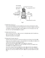
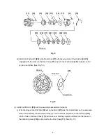
(3) Remove the Drill Chuck [2]. (See Fig. 4.)
(a) Turn the Motor [27] counterclockwise (when viewed from the rear) and remove it from the Rear Case
[17]. Remove the Shift Knob [39] from the Shift Arm [18]. Take care not to remove the Shift Arm
[18] from the Rear Case [17] in this operation.
(b) Mount the motor spacer (an accessory of the Special Repair Tool J-292) to the assembly of the Drill
Chuck [2], Cap [6], Front Case [11] and Rear Case [17] and then mount it to the Special Repair Tool
J-292 clamped in the vise as illustrated in Fig.4. In this operation, check that the pinion press-fitted
in the Special Repair Tool J-292 and the Planet Gear (A) [23] are engaged properly.
(c) Turn the Cap [6] clockwise (when viewed from the front) until it can turn no further. In this position
the drill mark “
” on the Cap [6] is positioned to the Shift Arm [18] side. Secure the Slide Ring
Gear [19] to the Front Case [11] side with the Shift Arm [18].
(d) Turn the sleeve of the Drill Chuck [2] counterclockwise (when viewed from the front) to fully open the
jaws of the Drill Chuck [2]. Turn the Special Screw M6 x 23 [1] clockwise and remove it. (Note that
the Special Screw is left-hand threaded.)
(e) Fit the hexagonal bar wrench for M10 into the Drill Chuck [2] as illustrated in Fig. 4 and remove the
Chuck by turning the bar wrench counterclockwise.


