--- 9 ---
8. PRECAUTIONS IN DISASSEMBLY AND REASSEMBLY
The [Bold] numbers in the descriptions below correspond to the item numbers in the Parts List and exploded
assembly diagram.
8-1. Disassembly
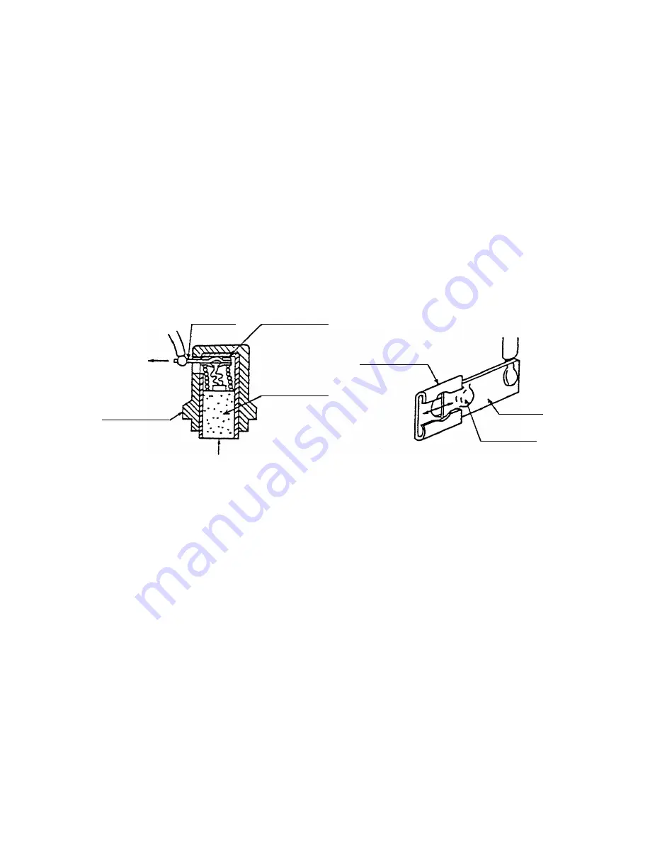
Fig. 5
Fig. 6
8-1-1. Motor section disassembly
(1) Removal of the handle cover
Loosen the Tapping Screw (W/Flange) D4 x 20 (Black) [31] and remove the Handle Cover [32].
(2) Removal of the carbon brushes
With a small flat-blade screwdriver, slightly lift the Brush Holders [36]. Then, while pushing the Carbon
Brushes [35] to the bottom of the Brush Holders [36], gently pull out and disconnect the internal wire
terminals. (Figs. 5 and 6)
(3) Removal of the gear cover from the housing
Loosen the Tapping Screw (W/Flange) D4 x 40 [10] and Tapping Screw (W/Flange) D4 x 55 [12], and
separate the Gear Cover [13] from the Housing [25]. Then, remove the Inner Cover [17] together with the
Armature [20] from the Housing [25].
Terminal
Carbon brush
Terminal
Brush Holder
Pull out
Carbon brush
stop piece
Carbon brush
stop piece
Projection
Push
Summary of Contents for DV 16V
Page 27: ......


