--- 10 ---
10. REPAIR GUIDE
Be sure to remove the storage batteries from the main body before servicing. Inadvertent triggering of the switch
with the storage battery connected will result in a danger of accidental turning of the motor.
10-1. Precautions in Disassembly and Reassembly
The [Bold] numbers in the description below correspond to the item numbers in the Parts List and exploded
assembly diagram for the Model DV 18DV.
10-1-1. Disassembly
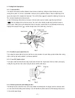
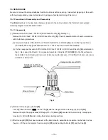
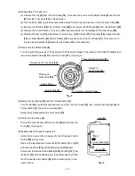
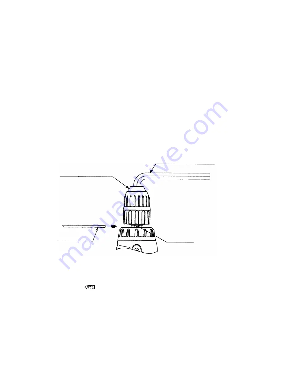
(1) Removal of the Drill Chuck 13VLRF-N (W/O Chuck Wrench) [2] (See Fig. 4.)
Remove the Drill Chuck 13VLRF-N (W/O Chuck Wrench) [2] of the fully assembled main body in accordance
with the following procedures.
(a) Fully open the jaws of the Drill Chuck 13VLRF-N (W/O Chuck Wrench) [2], and turn the Special Screw
(Left Hand) M6 x 23 [1] clockwise and remove it. Take care that it is left-hand threaded.
(b) Fix the hexagonal bar wrench M10 into the Drill Chuck 13VLRF-N (W/O Chuck Wrench) [2] as indicated in
Fig.4. Next, apply the Wrench 14 mm (special repair tool, Code No. 873929) [601] to the flat surfaces on
the spindle to hold it steady, and remove it by turning counterclockwise. If it is difficult to loosen, use a pipe
extension or similar tool.
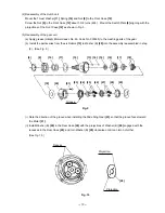
(2) Removal of Housing (A). (B) Set [35]
First, align the drill mark " " on the Cap [4] with the triangle mark on Housing (A). (B) Set [35].
Remove the eight Tapping Screws (W/Flange) D3 x 16 (Black) [32] secured to the main body. Gently open
Housing (A). (B) Set [35] while holding their battery loading sections.
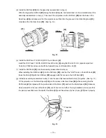
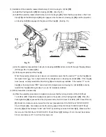
(3) After Housing (B) [35] has been removed, all the internal parts, assembled or separate, can be taken out as
they are. Lift the entire contents from Housing (A) [35] while holding the Motor [31] and the Cap [4].
Hexagonal bar wrench M10
Wrench 14 mm
Drill Chuck 13VLRF-N
(W/O Chuck Wrench) [2]
Flat surface
Fig. 4


