5-12
Disassembly and Reaasembly
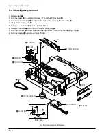
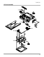
5-4-5 Ass'y Brkt Deck Removal
1) Remove Washer
Œ
.
2) Remove Gear Feed B
´
, Gear Feed A
ˇ
.
3) Remove 2 Screws
¨
.
4) Remove Shaft Pick-Up
ˆ
and Pick-Up Assy
Ø
.
5) Remove 1 Screw
∏
.
6) Remove 2 Screws
”
.
7) Remove 3 Spring Spindle
’
and Motor Spindle Ass'y
˝
.
Fig. 5-12 Ass'y Brkt Deck Removal
¨
2 SCREW
Œ
WASHER
´
GEAR FEED B
”
2 SCREWS
∏
1 SCREW
ˆ
SHAFT PICK-UP
ˇ
GEAR FEED A
Ø
PICK-UP ASS'Y
’
SPRING SPINDLE
˝
MOTOR SPINDLE
Summary of Contents for DV-P313U
Page 9: ...Product Specification 3 2 MEMO ...
Page 19: ...5 6 Disassembly and Reaasembly 5 2 PCB Location Fig 5 6 PCB Location ...
Page 34: ...8 1 8 Exploded View 8 1 Cabinet Assembly 8 2 Deck Assembly Page 8 2 8 3 ...
Page 36: ...Exploded Views 8 3 8 2 Deck Assembly 107 H220 H106 H207 H200 H210 ...
Page 37: ...Exploded Views 8 4 MEMO ...
Page 41: ...Block Diagram 10 2 MEMO ...
Page 42: ...11 1 11 PCB Diagrams 11 2 11 3 11 4 11 4 11 1 Main 11 2 Jack 11 3 Deck 11 4 Housing ...
Page 43: ...PCB Diagrams 11 2 11 1 Main COMPONENT SOLDER SIDE ...
Page 44: ...PCB Diagrams 11 3 11 2 Jack ...
Page 45: ...PCB Diagrams 11 4 11 3 Deck 11 4 Housing ...
Page 46: ...12 1 12 Wiring Diagram ...
Page 47: ...Wiring Diagram 12 2 MEMO ...
Page 49: ...Schematic Diagrams 13 2 13 1 Power ...
Page 50: ...Schematic Diagrams 13 3 13 2 AV Decoder Main Micom Key KEY ...
Page 51: ...Schematic Diagrams 13 4 13 3 Servo ...
Page 52: ...Schematic Diagrams 13 5 OPTION 13 4 Video ...
Page 53: ...Schematic Diagrams 13 6 OPTION OPTION 13 5 Audio ...
Page 54: ...Schematic Diagrams 13 7 OPTION OPTION 13 6 Front Micom VFD Display ...
Page 55: ...Schematic Diagrams 13 8 HOUSING PCB 13 7 Deck ...

