2 - 6
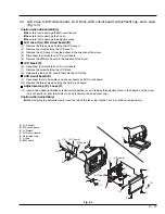
O-ring
Lens
OK
Lens surface
NG
(1)
(3)
(3)
(3)
(a)
(3)
(3)
(3)
(3)
(2)
L
A
B
C
(3)
(3)
(3)
(3)
PG1501
PG6101
M
(4)
(b)
(5)
(6)
(c)
(d)
(7)
(e)
D
N
C
[Bottom view]
[Rear view]
3.
Troubleshooting during Disassembly
3.1
Removing DVD-RAM/DVD-R disc
Perform the following procedure only when the disc loading block does not open (DVD-RAM/DVD-R disc cannot be removed)
when the DISC EJECT button is pressed.
Caution:
The disc loading block of DVD video camera/recorder will normally open even if power supply is not connected.
However, if the power supply is removed while the disc is being accessed, the disc loading block will not open.
Before starting the following procedure, supply power again, and make sure that access to disc is completed.
Perform the following procedure only when the disc loading block still does not open.
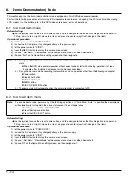
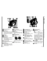
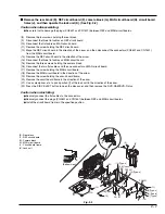
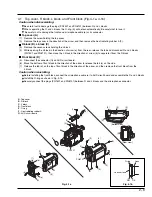
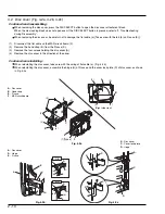
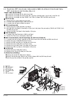
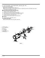
Remove the top cover (A), and then separate the R block (B), L block (C) and front block (D).
(See Fig. 3-1a, 3-1b)
Caution when disassembling:
Be careful not to damage the plugs (PG1501 and PG6101) between R and L blocks.
When separating the R and L blocks, the O-ring (L) will detach automatically: Be careful not to lose it.
Be careful not to damage the front case, microphone cable (e) or its connector.
(1)
Remove the screw holding the top cover.
(2)
Remove the top cover in the direction of the arrow, and then remove the heat radiating rubber A (M).
(3)
Remove the seven screws holding the L block.
(4)
While opening the L block in the direction of arrow (a) from the rear, release the tab at the top and disconnect R and
L blocks (PG1501 and PG6101); then move the L block in the direction of arrow (b) to separate it from the R block.
(5)
Disconnect the connector on AUD circuit board (N).
(6)
Move the bottom of front block in the direction of the arrow to release the tabs (c) on the side.
(7)
Release the tab (d) on the top of front block in the direction of the arrow, and then remove the front block from the
L block.
Caution when reinstalling:
Before installing the front block, connect the microphone cable (e) to AUD circuit board and assemble the R and L blocks.
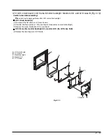
Install the O-ring as shown in Fig. 3-1b.
Securely connect the plugs (PG1501 and PG6101) between R and L blocks and the microphone connector.
Fig. 3-1a
Fig. 3-1b
A : Top cover
B : R block
C : L block
D : Front block
L : O-ring
M : Heat radiating
rubber A
N : AUD circuit board

