2 - 9
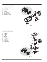
O-ring
Lens
OK
Lens surface
NG
(1)
(3)
(3)
(3)
(a)
(3)
(3)
(3)
(3)
(2)
E
A
B
C
(3)
(3)
(3)
(3)
PG1501
PG6101
F
(4)
(b)
(5)
(6)
(c)
(d)
(7)
(e)
D
G
C
[Bottom view]
[Rear view]
4.1
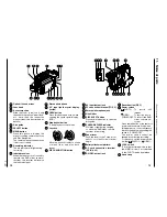
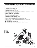
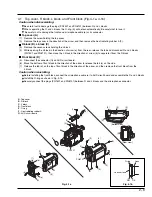
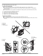
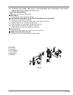
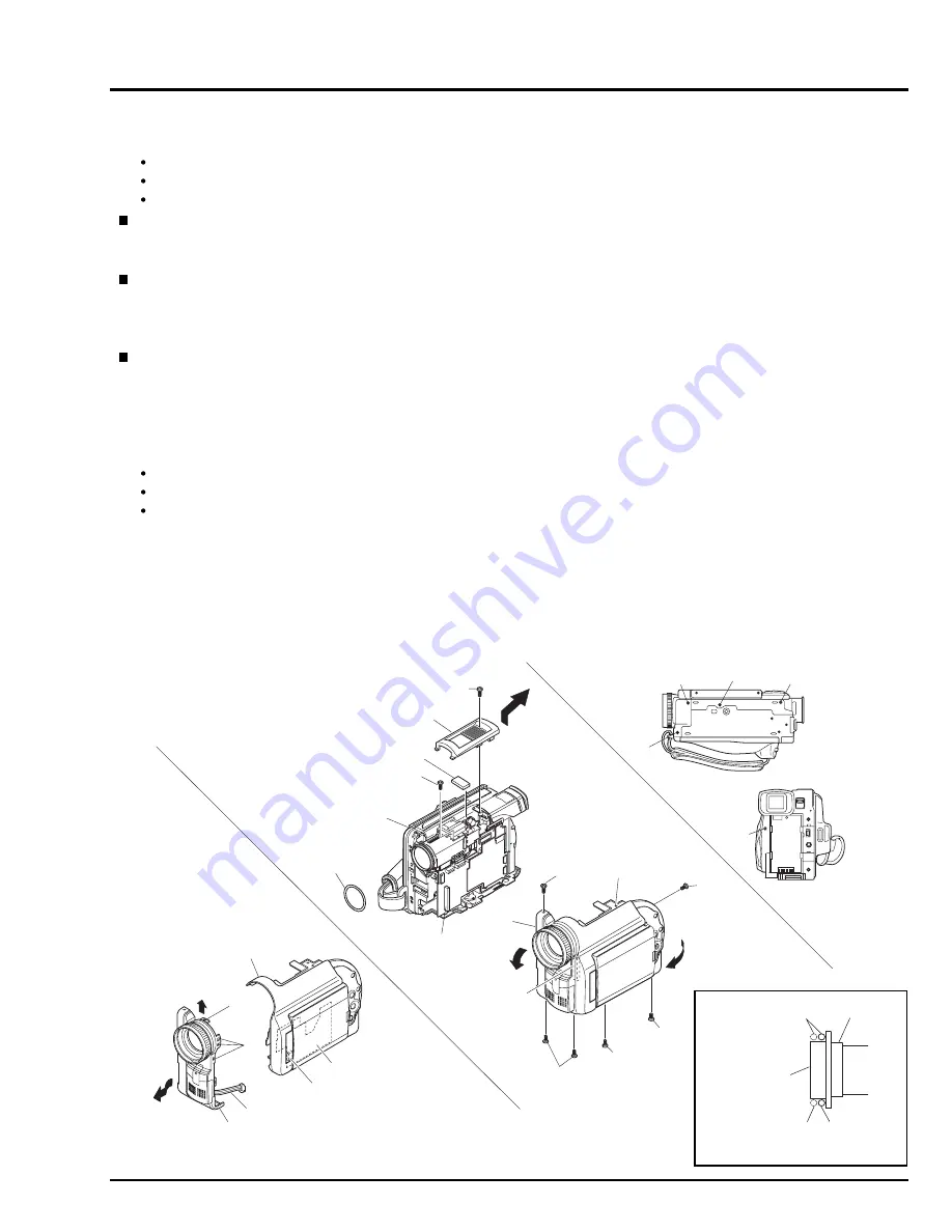
Top cover, R block, L block, and Front block (Fig. 4-1a, 4-1b)
Caution when disassembling:
Be careful not to damage the plugs (PG1501 and PG6101) between R and L blocks.
When separating the R and L blocks, the O-ring (E) will detach automatically: Be careful not to lose it.
Be careful not to damage the front case, microphone cable (e) or its connector.
Top cover (A)
(1)
Remove the screw holding the top cover.
(2)
Remove the top cover in the direction of the arrow, and then remove the heat radiating rubber A (F).
R block (B), L block (C)
(3)
Remove the seven screws holding the L block.
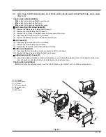
(4)
While opening the L block in the direction of arrow (a) from the rear, release the tab and disconnect R and L blocks
(PG1501 and PG6101); then move the L block in the direction of arrow (b) to separate it from the R block.
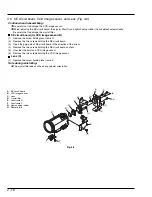
Front block (D)
(5)
Disconnect the connector (G) on AUD circuit board.
(6)
Move the bottom of front block in the direction of the arrow to release the tab (c) on the side.
(7)
Release the tab (d) on the top of front block in the direction of the arrow, and then remove the front block from the
L block.
Caution when reinstalling:
Before installing the front block, connect the microphone cable (e) to AUD circuit board and assemble the R and L blocks.
Install the O-ring as shown in Fig. 3-1b.
Securely connect the plugs (PG1501 and PG6101) between R and L blocks and the microphone connector.
A : Top cover
B : R block
C : L block
D : Front block
E : O-ring
F : Heat radiating rubber A
G : AUD circuit board
Fig. 4-1a
Fig. 4-1b


