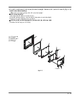
2 - 16
C
D
B
A
(4)
(4)
(1)
(7)
(2)
(2)
(3)
(5)
(6)
E
F
G
H
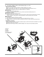
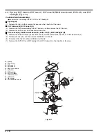
4.9
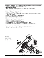
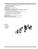
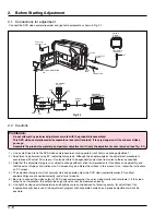
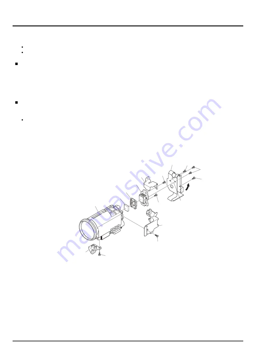
SE circuit board, CCD image sensor, and Lens (Fig. 4-9)
Caution when disassembling:
Be careful not to damage the CCD image sensor.
When removing the SE circuit board, the crystal filter (D) and light shading rubber (G) will detach automatically:
Be careful not to damage the crystal filter.
SE circuit board (A), CCD image sensor (B)
(1)
Remove the screw holding lens frame R.
(2)
Remove the two screws holding the SE circuit board.
(3)
Open the gyro side of SE circuit board in the direction of the arrow.
(4)
Remove the two screws holding the SE circuit board and lens.
(5)
Unsolder the points on CCD image sensor.
(6)
Remove the two screws holding the CCD image sensor.
Lens (C)
(7)
Remove the screw holding lens frame F.
Note during reinstalling:
The crystal filter does not have any special orientation.
A : SE circuit board
B : CCD image sensor
C : Lens
D : Crystal filter
E : Lens frame R
F : Lens frame F
G : Light shading rubber
H : Sensor plate
Fig. 4-9

