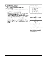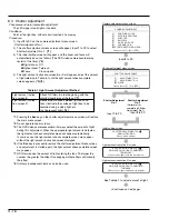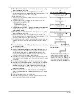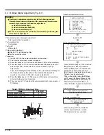
3 - 7
Electric Circuit Adjustment
1.
Test Equipment/Jigs Necessary for Adjustment
1.1
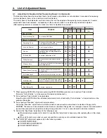
List of jigs and tools
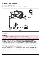
The following table shows the jigs and tools, some of them new, used for servicing (electrically adjusting) the DVD video
camera/recorder.
[
New]
Adjustment Floppy disk
No. TP13871
[
New]
MV-230 Connection
Cable (*2) No. TP13881
DSP-R Jig No. 7099448
C12 Light Balancing Filter
(Diameter: 46 mm)
No. 7099369
Personal Computer (*1)
[generally available]
RS-232C Cable
(9-pin or 25-pin straight type)
[generally available]
ND2/ND4/ND8 Filters (*3)
(Diameter: 46 mm)
[generally available]
AV Output Cable
[Accessory (provided)]
*1: Personal Computer will be abbreviated as PC hereafter.
*2: The actual jig shape may be different from the illustration, since it might have been changed to improve workability.
*3: The filters may be used in "6.3 Shutter Adjustment".
1.2
List of charts for adjustment
1.3
Test equipment, etc.
Color video monitor (color TV with AV input jacks)
Oscilloscope
Vectorscope (*1)
Digital voltmeter (DVM)
Frequency counter
3100 K light box
AC adapter
DC power supply (5 V/1 A) (*2)
Lighting device, such as a video light (not fluorescent light) (*3)
*1: Adjustment is possible without a vectorscope, but more precise adjustment can be made if it is used.
*2: The DC power supply is used to power the DSP-R jig.
*3: This may be used in "6.3 Shutter Adjustment".
Color bar chart
Grayscale chart
Backfocus chart

