3 - 8
MV230 CONNECTION
JIG
WHT
WHT
YEL
YEL
BLK
BLK
BLK
DC POWER
SUPPLY
(5V/1A)
RED
RS232C
CABLE
DSP-R JIG
PERSONAL
COMPUTER(PC)
AC ADAPTER
AV OUTPUT
CABLE
COLOR
VIDEO
MONITER
YEL
Remove the
adjustment cap
TO VIDEO IN
TERMINAL
DC IN
JACK
A/V JACK
2.
Before Starting Adjustment
2.1
Connections for adjustment
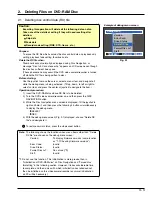
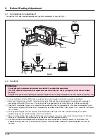
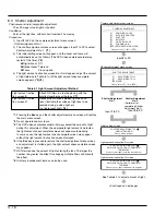
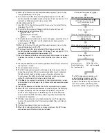
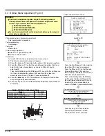
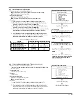
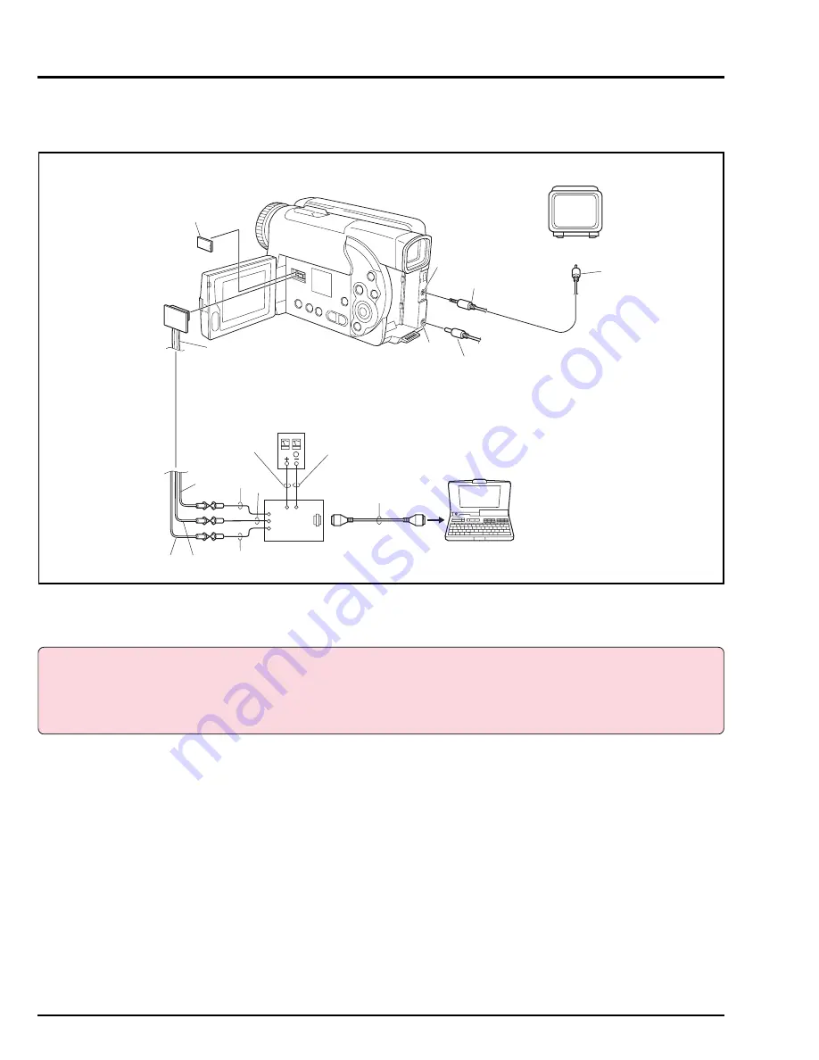
Connect the DVD video camera/recorder and jigs/test equipment as shown in Fig. 2-1.
Fig. 2-1
2.2
Cautions
Prohibition:
Do not attempt any perform adjustment or work with the product disassembled.
This DVD video camera/recorder incorporates a laser emitter block: It is very dangerous if laser beam strikes
your eye.
Assemble the product completely, and perform adjustment with only the adjustment cover removed (see Fig. 2-1).
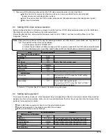
1) Use a small tripod to fix the DVD video camera/recorder, making certain it will not move during adjustment.
2) Adjustment is performed using PC (adjustment program). Although this chapter explains the adjustment procedure in
accordance with actual PC screens, it is also possible to independently adjust one item unless otherwise specified.
3) Note that the adjustment program is subject to change without notice for improvements in functions and operability, and
that the actual displays (instructions) on PC screen may be different from those in this manual: If so, follow the instructions
on PC screen.
4) The adjustment program will not normally start and operate unless the DVD video camera/recorder, PC and test
equipment/jigs are connected correctly, and all are turned on.
5) Be sure to connect the video output of DVD video camera/recorder to a color video monitor and terminate it: If the video
output is not terminated, the output video signal level cannot be measured correctly.
6) Use light box whose color temperature and brightness are controlled and no flickering occurs, for adjustment. If an
inappropriate light box is used, the adjustment program will not operate normally, and precise adjustment will not be
possible.

