E2 - 12
3.7
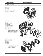
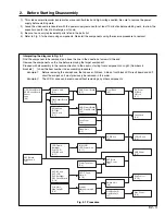
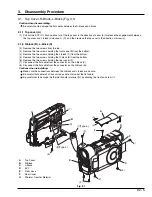
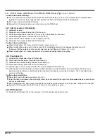
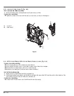
Link Bracket R, Link Bracket L, Loader, Mechanism Unit (Figs. 3-7-1, 3-7-2)
Cautions when disassembling:
Do not turn power on.
Do not dismantle any of the components in mechanism unit.
Do not subject the mechanism unit and loader to impact or force.
Dismantle and reinstall the link brackets L/R and mechanism unit and loader with the disc loading block kept open, by
pressing the EJECT button. If the disc loading block does not open, refer to “3. Disassembly When Trouble Has
Occurred”.
Be careful not to damage any of the connector cables (flat cables).
Be careful not to damage the thermal transfer material between the mechanism unit and side case-R.
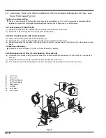
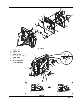
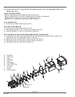
3.7.1 Link bracket R (A), Link bracket L (B)
(1) Remove the four screws holding link brackets R (A) and L (B).
Caution when reinstalling:
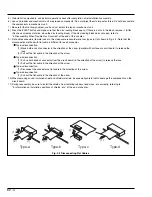
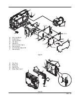
Check the arm and shaft installation positions on link brackets R/L (see Fig. 3-7-2): The link brackets R/L are symmetrical
on the right and left, and must be installed in the same way.
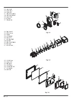
3.7.2 Loader (C), Mechanism unit (D)
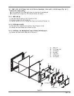
(2) Remove the tape that fixes the thermal transfer material (E), taking care not to damage the thermal transfer material (E).
(3) Disconnect one connector on the circuit board in mechanism unit (D).
(4) Remove the screw.
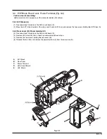
(5) Align portion (a) of link (G) with boss of side case-R (H), and remove link (G) from side case-R (see Fig. 3-7-2)
(6) Fully open plate of side case-R (I) in the direction of the arrow.
(7) Remove the four screws holding the loader (C) and mechanism unit (D).
(8) Remove the two screws and unsolder one point: Remove the mecha. shield (F).
(9) Remove the two screws holding the loader (C) and remove the loader from the mechanism unit (D).
Cautions when reinstalling:
Install the loader unit securely and tighten the four fixing screws evenly.
When installing the link (G), be careful not to damage the components on the mechanism unit and loader.


