Appendix
A - 10
A.3.3
Basic specification of transmission control procedure
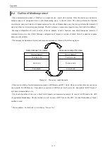
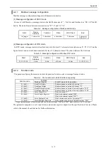
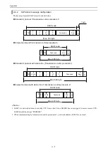
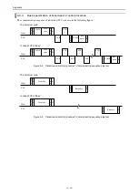
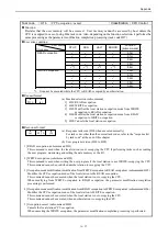
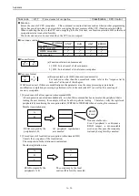
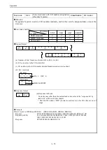
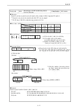
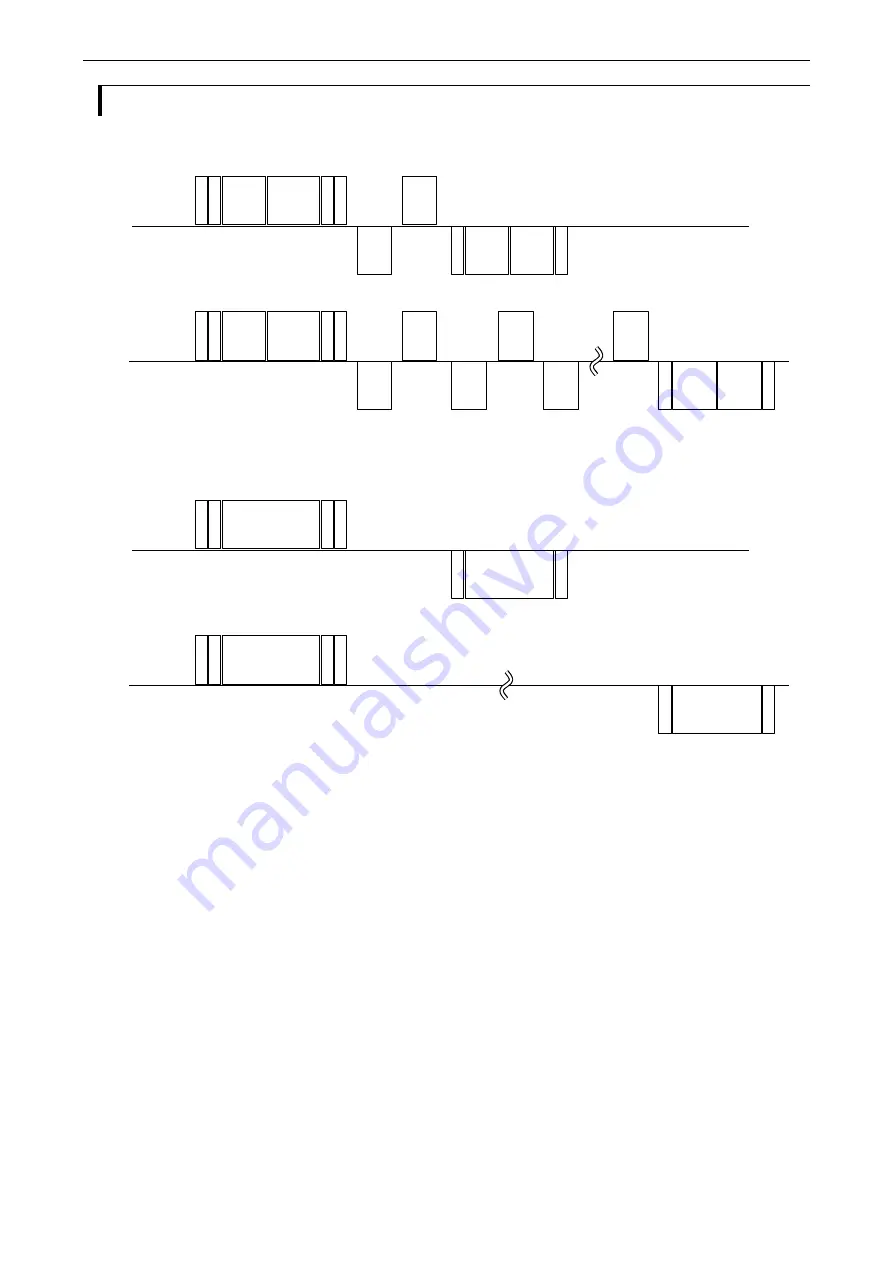
The communication sequence of a host and PLC is shown in the following figure.
Host
PLC
ACK
T
M
LUMP
Task
code
S
u
m
S
T
X
S
T
X
C
R
Res-
ponse
ENQ
1
The minimum cycle
In case of CPU
“Busy”
EOT
ENQ
1
EOT
LUMP
C
R
Host
PLC
T
M
LUMP
Task
code
S
u
m
S
T
X
C
R
ACK
ENQ
1
ENQ
1
S
T
X
Res-
ponse
LUMP
C
R
Figure.A.5 Transmission control procedure 1 Communication sequence diagram
Host
PLC
T
M
Task code
S
u
m
S
T
X
S
T
X
C
R
Response
The minimum cycle
In case of CPU
“Busy”
C
R
Host
PLC
T
M
Task code
S
u
m
S
T
X
C
R
S
T
X
Response
C
R
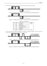
Figure.A.6 Transmission control procedure 2 Communication sequence diagram
Summary of Contents for EH-150 Series
Page 2: ......
Page 10: ...M E M O ...
Page 30: ...Chapter 4 Installation 4 10 M E M O ...
Page 156: ...Chapter 7 System setup 7 12 M E M O ...
Page 164: ...Chapter 8 Daily and Periodic Inspection 8 8 M E M O ...

