Chapter 5 Control of EH-SIO
5 - 9
5.2.1
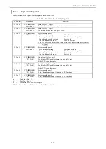
Register configuration
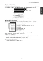
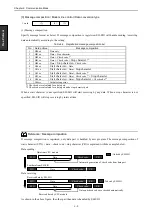
The function of the input / output register is shown below.
Table 5.1 Function of Input / Output register
Word No
Direction
Function
WX u s 0
CPU
EH-SIO
(CPU Read)
Status register for port 1
The data about the state of a port 1 is set.
WX u s 1
CPU
EH-SIO
(CPU Read)
Status register for port 2
The data about the state of a port 2 is set.
WX u s 2
CPU
EH-SIO
(CPU Read)
System area for port 1
Before initial setting :
Used by system
In free protocol mode :
Number of receive packets
In dedicated procedure mode :
Error code
In Simple data link mode :
Used by system
Note : An error code is indicated when serious failure occurs in the system of
EH-SIO.
WX u s 3
CPU
EH-SIO
(CPU Read)
System area for port 2
Before initial setting :
Software version
In free protocol mode :
Number of receive packets
In dedicated procedure mode :
Error code
In Simple data link mode :
Error code
WY u s 4
CPU
EH-SIO
(CPU Write)
Control register for port 1
The data for CPU module controlling a port 1 is set.
Set by CPU module or user.
WY u s 5
CPU
EH-SIO
(CPU Write)
Control register for port 2
The data for CPU module controlling a port 2 is set.
Set by CPU module or user.
WY u s 6
CPU
EH-SIO
(CPU Write)
System area for port 1
Note: Please do not write. It is used by CPU module
WY u s 7
CPU
EH-SIO
(CPU Write)
System area for port 2
Note: Please do not write. It is used by CPU module
u
:
Unit No. ( 0 to 4 )
s
:
Slot No. ( 0 to 7 )
0 ~ 7 : Word No. which EH-SIO occupies
*Dedicated procedure
Modbus slave mode, Hi-Protocol mode
Summary of Contents for EH-150 Series
Page 2: ......
Page 10: ...M E M O ...
Page 30: ...Chapter 4 Installation 4 10 M E M O ...
Page 156: ...Chapter 7 System setup 7 12 M E M O ...
Page 164: ...Chapter 8 Daily and Periodic Inspection 8 8 M E M O ...

