Chapter6 Communication Mode
6 - 9
F
ree
P
ro
to
col
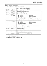
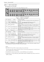
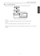
(2) Modem line control
Specify whether the state of the control signal (RS, ER) is always set to high or switched by user program.
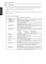
Table 6.3 Control list of registration modem lines
No.
Set value
Modem line control
1
Hxx0x
RS, ER always high
2
Hxx1x
RS, ER follows the state of RS and ER flag of control register.
-
Others
Initial setting error
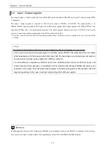
This setting is effective only when using the RS-232C port. When port1 or port 2 is used as RS-422/485, please
set "0".
Regardless of the above setting, RS and ER will be turned off automatically when an error occurs in EH-SIO and
receiving buffer is full.
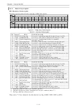
(3) Data conversion type
EH-SIO has data conversion function. Specify the conversion type as below.
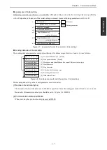
Table 6.4 Registration data conversion type list
No.
Set Value
Data conversion type
1
Hxxx0
Through (no conversion)
2
Hxxx1
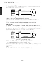
Binary / ASCII conversion (CPU / Binary
EH-SIO / ASCII)
3
Hxxx2
Binary through (CPU / Binary
EH-SIO / Binary)
-
Others
Initial setting error
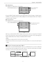
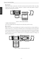
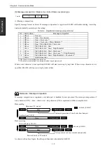
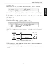
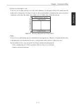
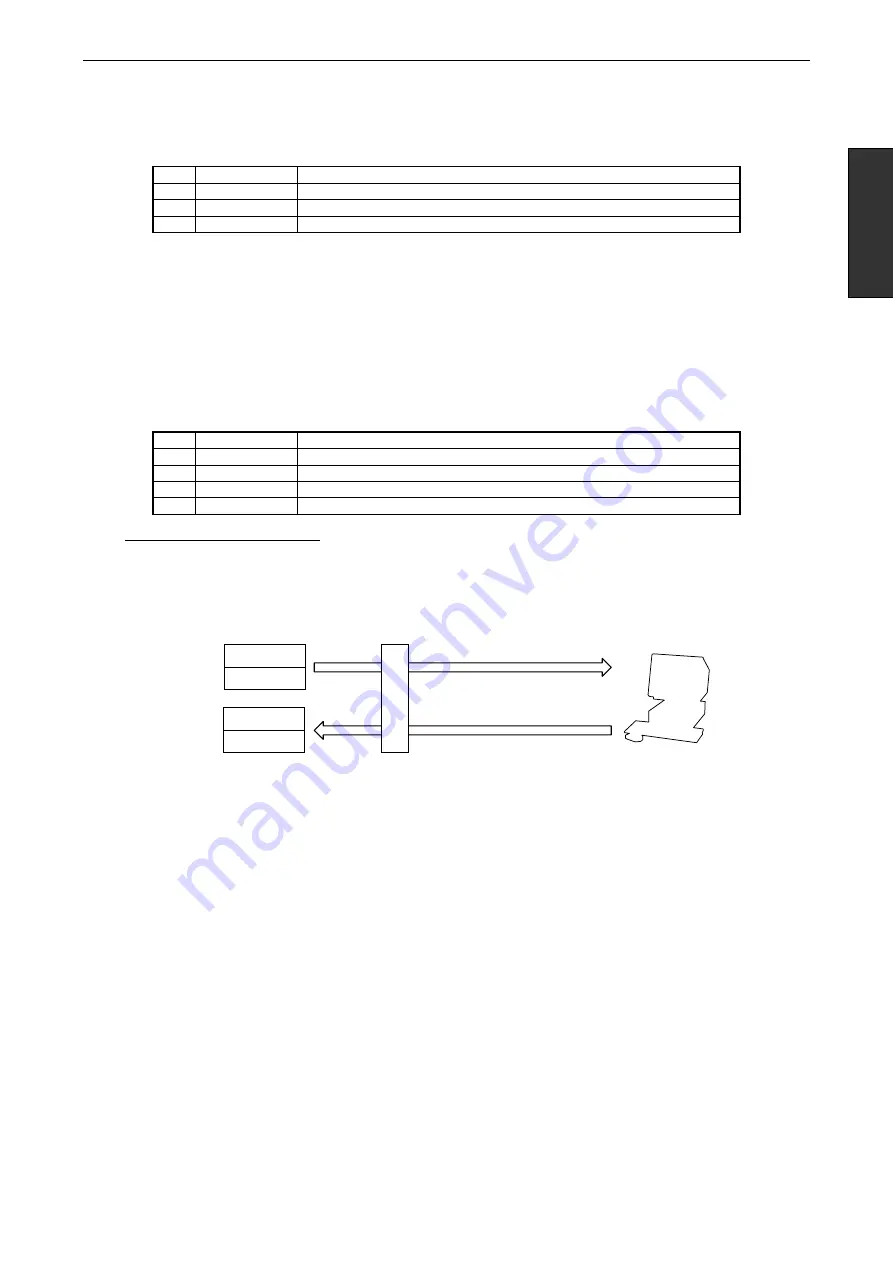
Through type (no conversion) :
The data stored in sending data area are transmitted as is, and the received data are stored in receiving data area
as is.
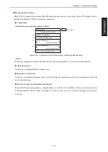
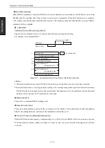
Figure 6.9 Example of through type (no conversion)
« Note »
Caution is necessary when using a message composition with start/stop characters since those parts will be
considered as starting and stopping points.
When using 7-bit transmission format configuration, the data of H80-HFF cannot be transmitted and received
correctly.
CPU module
H3031
H1234
EH-SIO
30 31 12 34
External device
41 42 AB CD
H4142
HABCD
No
c
o
n
v
ersio
n
Summary of Contents for EH-150 Series
Page 2: ......
Page 10: ...M E M O ...
Page 30: ...Chapter 4 Installation 4 10 M E M O ...
Page 156: ...Chapter 7 System setup 7 12 M E M O ...
Page 164: ...Chapter 8 Daily and Periodic Inspection 8 8 M E M O ...

