Chapter 6 Communication Mode
6 - 56
Mod
b
u
s S
lav
e
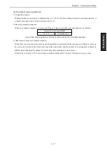
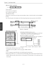
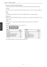
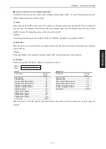
[4] Device address / waiting time
(1) Device address
Set device address in the high byte.
Note : No.00 is not possible to set.
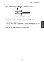
(2) Waiting time [
10ms]
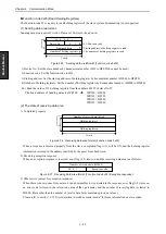
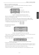
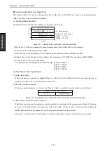
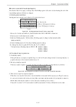
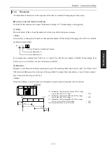
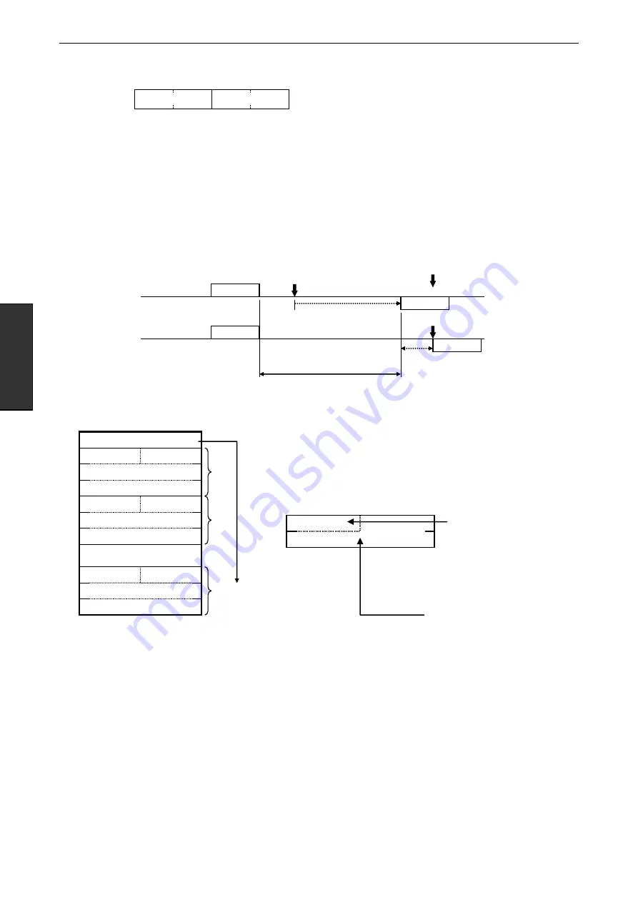
Waiting time is a time between receiving a query and sending a response. Actual waiting time is set time multiplied
by 10ms.
Note : The waiting time is the minimum value. It takes longer depending on system processing time of EH-SIO.
Figure 6.54 Waiting time
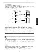
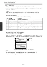
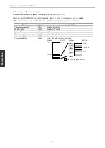
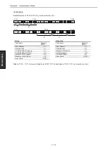
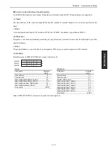
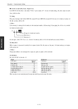
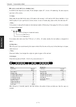
[5] I/O Mapping information (Bit)
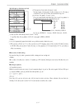
(1) The number of bit table divisions (1 word)
The maximum of the number of table divisions is 10. If a larger
value than 10 is set up, it will become an initial setting error.
(2) I/O Code / I/O address (2 word / 1 class)
I/O
code
is specified from the high byte of 1st word. A top address is
specified from low byte of 1st word and 2nd word.
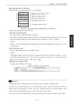
Ex) In case of Y20316 1st word … H0120, 2nd word … H0310
(3) Address offset of Modbus protocol (1 word / 1 class)
It specifies where the top address of I/O of (2) is mapped. (H0000 to HFFFF)
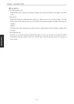
« Note »
(2), (3) of parameter prepares the number set up with the number of table divisions.
When you use software ver. 1.0, or when you do not use I/O mapping, please set the number of bit table divisions
as H0000. When the number of table divisions is 0, the parameter of I/O classification, I/O No., and address offset
is unnecessary.
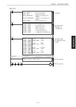
I/O code :
X
H00
Y
H01
R
H02
L
H03
M
H04
Timer / Counter
H05
CL
H06
I/O No. : H000000 to HFFFFFF
…
I/O address
I/O code
Address offset
I/O address
I/O code
Address offset
I/O address
I/O code
Address offset
Number of bit table divisions
1
n (Max.10)
2
(1)
1 word
(2)
Response
Configured waiting time
Query
Response
Query
Shifted
Shifted due to system
processing.
: Ready to respond
Summary of Contents for EH-150 Series
Page 2: ......
Page 10: ...M E M O ...
Page 30: ...Chapter 4 Installation 4 10 M E M O ...
Page 156: ...Chapter 7 System setup 7 12 M E M O ...
Page 164: ...Chapter 8 Daily and Periodic Inspection 8 8 M E M O ...

