Chapter.4 System equipment
4-3
4.2 LED
indications
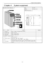
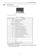
Figure 4.1 shows out view of the LED cover.
STS
RX1
RX2
OP4
POW
TX1
TX2
OP3
EH-ETH2
ETHERNET
WDE
TSK
OP1
OP5
ERR
IER
OP2
OP6
Figure 4.1
Out view of the LED cover
Table 4.3 shows LED indications.
Table 4.3
LED indications
Name Indication
Description
ON
The module is in Normal operation mode.
Blinking
The module is in Utility mode.
POW
OFF
No Power is applied.
ON
The module is OK.
Slow Blinking The module detected an error.
(*1)
Fast Blinking The module is in resetting process.
(*2)
STS
OFF
No Power is applied.
ON
The module detected Watchdog timer error.
WDE
OFF
The system software is running properly.
ON
The module detected communication error.
ERR
OFF
The module does not detect communication error.
ON
The module is sending data in Ethernet port.
TX1
OFF
The module is not sending data in Ethernet port.
ON
The module is receiving data in Ethernet port.
RX1
OFF
The module is not receiving data in Ethernet port.
ON
At least one of task code port is opened. (TCP/IP only)
TSK
OFF
None of task code port is opened.
ON
The module detected parameter error.
IER
OFF
The module does not detect parameter error.
TX2 OFF
Unused.
RX2 OFF
Unused.
ON
ASR port No.1 to 6 is opened.
OP1 to 6
OFF
ASR port No.1 to 6 is closed.
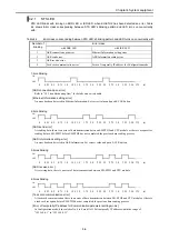
*1: Regarding details, refer to 4.2.1 “STS LED”
*2: When the power activation, STS LED turns on or fast blinking. If I/O assignment on CPU is done
correctly, STS LED’s fast blinking changes to lighting after reset process. If I/O assignment on CPU is
not done, STS LED keeps fast blinking.


